Table of Contents
Overview
This is an example of VRF-aware DMVPN configuration that uses FVRF. Understand the meaning of configuring NHRP with multipoint GRE tunnels.
Related article
Please also see the following article about configuring DMVPN with FVRF.
Network Diagram
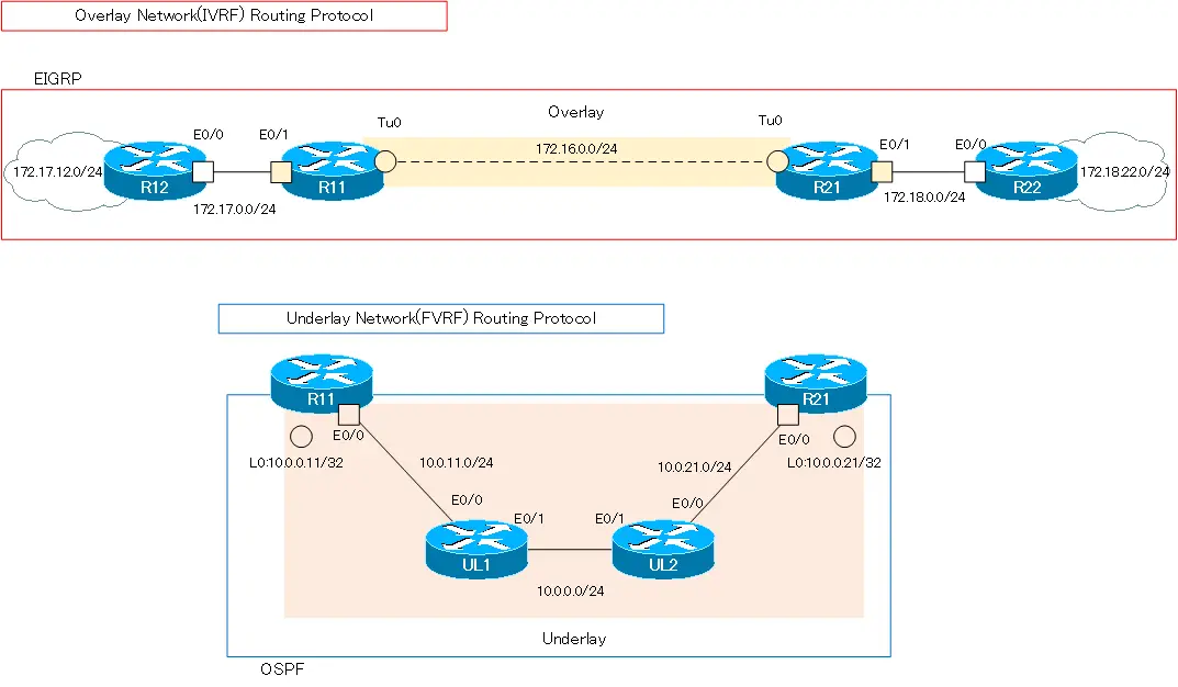
Consider the following network diagram. The network diagram is the same as in “IPSec VTI : with FVRF Configuration Example“. The underlay network in this network diagram is not the Internet, but is assumed to be the Internet. Also, although multipoint GRE tunnels is used, only R11/R21 are in the overlay network to simplify the story.

Configuration conditions
Build DMVPN overlay network between R11 and R21, with R11 as NHS (Next Hop Server) and R21 as NHC (Next Hop Client). Then, separate the overlay network from the underlay network with VRF; as VRF, configure the following
| Router | VRF name | RD | Interface |
|---|---|---|---|
| R11 | FVRF | 65001:100 | Lo0 Eth0/0 |
| IVRF | 65001:200 | Tunnel0 Eth0/1 | |
| R21 | FVRF | 65001:100 | Lo0 Eth0/0 |
| IVRF | 65001:200 | Tunnel0 Eth0/1 |
In addition, the address ranges of IVRF in the overlay network and FVRF in the underlay network do not overlap. IVRF is addressing with Class B private addresses such as 172.16.x.x and 172.17.x.x and 172.18.x.x. And FVRF is addressing with class A private addresses of 10.x.x.x.
As routing protocols, IVRF uses EIGRP and FVRF uses OSPF.
| Address Range | Routing Protocol | |
|---|---|---|
| Overlay Network(IVRF) | 172.16.0.0/16 172.17.0.0/16 172.18.0.0/16 | EIGRP |
| Underlay Network(FVRF) | 10.0.0.0/8 | OSPF |
Overlay network data is encrypted with IPSec and transferred over the underlay network. The various IPSec parameters are as follows
| Encryption algorithm | 3DES |
| Hash Algorithm | MD5 |
| Peer Authentication | PSK |
| DH group | 2 |
| Security protocol | ESP |
| Encryption algorithm | 3DES |
| Hash Algorithm | MD5 |
Initial Configuration
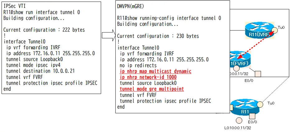
Start with overlay network with IPSec VTI between R11 and R21 separated by VRF. This is the completion stage of “IPSec VTI with FVRF Configuration Example“. Focus on configuration for change from IPSec VTI to DMVPN.
R11 Configuration Excerpts (Click)
hostname R11
!
ip vrf FVRF
 rd 65001:100
!
ip vrf IVRF
 rd 65001:200
!
crypto keyring KEY vrf FVRF
  pre-shared-key address 10.0.0.21 key cisco
!
crypto isakmp policy 10
 encr 3des
 hash md5
 authentication pre-share
 group 2
!
crypto ipsec transform-set TS esp-3des esp-md5-hmac
 mode tunnel
!
crypto ipsec profile IPSEC
 set transform-set TS
!

interface Loopback0
 ip vrf forwarding FVRF
 ip address 10.0.0.11 255.255.255.255
!
interface Tunnel0
 ip vrf forwarding IVRF
 ip address 172.16.0.11 255.255.255.0
 tunnel source Loopback0
 tunnel mode ipsec ipv4
 tunnel destination 10.0.0.21
 tunnel vrf FVRF
 tunnel protection ipsec profile IPSEC
!
interface Ethernet0/0
 ip vrf forwarding FVRF
 ip address 10.0.11.11 255.255.255.0
!
interface Ethernet0/1
 ip vrf forwarding IVRF
 ip address 172.17.0.11 255.255.255.0
!
router eigrp 1
 !
 address-family ipv4 vrf IVRF autonomous-system 1
  network 172.16.0.0
  network 172.17.0.0
 exit-address-family
 eigrp router-id 11.11.11.11
!
router ospf 1 vrf FVRF
 router-id 11.11.11.11
 network 10.0.0.11 0.0.0.0 area 0
 network 10.0.11.11 0.0.0.0 area 0
R21 Configuration Excerpts (Click)
hostname R21
!
ip vrf FVRF
 rd 65100:100
!
ip vrf IVRF
 rd 65100:200
!
crypto keyring KEY vrf FVRF
  pre-shared-key address 10.0.0.11 key cisco
!
crypto isakmp policy 10
 encr 3des
 hash md5
 authentication pre-share
 group 2
!
crypto ipsec transform-set TS esp-3des esp-md5-hmac
 mode tunnel
!
crypto ipsec profile IPSEC
 set transform-set TS
!
interface Loopback0
 ip vrf forwarding FVRF
 ip address 10.0.0.21 255.255.255.255
!
interface Tunnel0
 ip vrf forwarding IVRF
 ip address 172.16.0.21 255.255.255.0
 tunnel source Loopback0
 tunnel mode ipsec ipv4
 tunnel destination 10.0.0.11
 tunnel vrf FVRF
 tunnel protection ipsec profile IPSEC
!
interface Ethernet0/0
 ip vrf forwarding FVRF
 ip address 10.0.21.21 255.255.255.0
!
interface Ethernet0/1
 ip vrf forwarding IVRF
 ip address 172.18.0.21 255.255.255.0
!
router eigrp 1
 !
 address-family ipv4 vrf IVRF autonomous-system 1
  network 172.16.0.0
  network 172.18.0.0
 exit-address-family
 eigrp router-id 21.21.21.21
!
router ospf 1 vrf FVRF
 router-id 21.21.21.21
 network 10.0.0.21 0.0.0.0 area 0
 network 10.0.21.21 0.0.0.0 area 0
R12 Configuration Excerpts (Click)
hostname R12
!
interface Loopback0
 ip address 172.17.12.12 255.255.255.0
 ip ospf network point-to-point
!
interface Ethernet0/0
 ip address 172.17.0.12 255.255.255.0
!
router eigrp 1
 network 172.17.0.0
 eigrp router-id 12.12.12.12
R22 Configuration Excerpts (Click)
hostname R22
!
interface Loopback0
 ip address 172.18.22.22 255.255.255.0
 ip ospf network point-to-point
!
interface Ethernet0/0
 ip address 172.18.0.22 255.255.255.0
!
router eigrp 1
 network 172.18.0.0
 eigrp router-id 22.22.22.22
UL1 Configuration Excerpts (Click)
hostname UL1
!
interface Ethernet0/0
 ip address 10.0.11.1 255.255.255.0
!
interface Ethernet0/1
 ip address 10.0.0.1 255.255.255.0
!
router ospf 1
 router-id 1.1.1.1
 network 10.0.0.0 0.255.255.255 area 0
UL2 Configuration Excerpts (Click)
hostname UL2
!
interface Ethernet0/0
 ip address 10.0.21.2 255.255.255.0
!
interface Ethernet0/1
 ip address 10.0.0.2 255.255.255.0
!
router ospf 1
 router-id 2.2.2.2
 network 10.0.0.0 0.255.255.255 area 0
Related article
Initial configuration is the completion stage of the following article.

Configuration and Verification
Step1: R11 mGRE NHS Configuration
Change the Tunnel0 interface of R11 to mGRE. As an NHS, R11 manages the correspondence of overlay addresses to underlay addresses. In addition, the multicast packets output from Tunnel0 are encapsulated with the underlay address of the NHC, which is dynamically registered by NHRP.
R11 mGRE NHS Configuration
interface Tunnel 0
 no tunnel destination
 tunnel mode gre multipoint
 ip nhrp network-id 1000
 ip nhrp map multicast dynamic
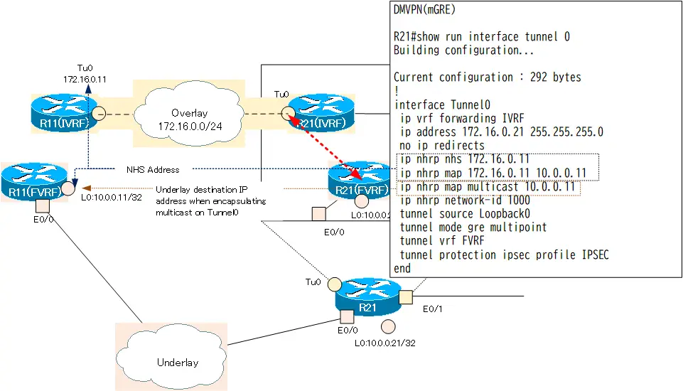
Step2: R21 mGRE NHC Configuration
Change the Tunnel0 interface of R21 to mGRE. R21 is configured as NHC. Specify R11 as the NHS that manages the correspondence between overlay and underlay addresses. In addition, the multicast packets output from Tunnel0 are encapsulated with the underlay address (10.0.0.11) of R11.
R21 mGRE NHC Configuration
interface Tunnel 0
 no tunnel destination
 tunnel mode gre multipoint
 ip nhrp network-id 1000
 ip nhrp nhs 172.16.0.11
 ip nhrp map 172.16.0.11 10.0.0.11
 ip nhrp map multicast 10.0.0.11
Step3: crypto keyring Configuration
Since only R11 and R21 are used, IPSec communication is possible with the current crypto keyring configuration. To establish a dynamic IPSec peer, change the crypto keyring configuration so that the IP address of the peer is not explicitly specified.
R11 crypto keyring Configuration
crypto keyring KEY vrf FVRF
  no pre-shared-key address 10.0.0.21 key cisco
  pre-shared-key address 0.0.0.0 0.0.0.0 key cisco
R21 crypto keyring Configuration
crypto keyring KEY vrf FVRF
  no pre-shared-key address 10.0.0.11 key cisco
  pre-shared-key address 0.0.0.0 0.0.0.0 key cisco
Step4: IPSec Transfrom set Configuration
Change the mode of the current IPSec transform set “TS” to transport mode to reduce the overhead of encapsulating headers.
R11/R21 IPSec Transform set Configuration
crypto ipsec transform-set TS esp-3des esp-md5-hmac
 mode transport
Step5: DMVPN Verification
Use the following show command to verify DMVPN configuration and operation.
- show interface tunnel 0
- show dmvpn
- show ip nhrp
- show ip eigrp vrf IVRF neighbor
- show ip route vrf IVRF
On R11, the following is provided.
R11 DMVPN Verification
R11#show interfaces tunnel 0
Tunnel0 is up, line protocol is up
  Hardware is Tunnel
  Internet address is 172.16.0.11/24
  MTU 17916 bytes, BW 100 Kbit/sec, DLY 50000 usec,
     reliability 255/255, txload 1/255, rxload 1/255
  Encapsulation TUNNEL, loopback not set
  Keepalive not set
  Tunnel linestate evaluation up
  Tunnel source 10.0.0.11 (Loopback0)
   Tunnel Subblocks:
      src-track:
         Tunnel0 source tracking subblock associated with Loopback0
          Set of tunnels with source Loopback0, 1 member (includes iterators), on interface
  Tunnel protocol/transport multi-GRE/IP
    Key disabled, sequencing disabled
    Checksumming of packets disabled
  Tunnel TTL 255, Fast tunneling enabled
  Tunnel transport MTU 1476 bytes
  Tunnel transmit bandwidth 8000 (kbps)
  Tunnel receive bandwidth 8000 (kbps)
  Tunnel protection via IPSec (profile "IPSEC")
-- omitted --
R11#show dmvpn
Legend: Attrb --> S - Static, D - Dynamic, I - Incomplete
        N - NATed, L - Local, X - No Socket
        T1 - Route Installed, T2 - Nexthop-override
        C - CTS Capable
        # Ent --> Number of NHRP entries with same NBMA peer
        NHS Status: E --> Expecting Replies, R --> Responding, W --> Waiting
        UpDn Time --> Up or Down Time for a Tunnel
==========================================================================

Interface: Tunnel0, IPv4 NHRP Details
Type:Hub, NHRP Peers:1,

 # Ent  Peer NBMA Addr Peer Tunnel Add State  UpDn Tm Attrb
 ----- --------------- --------------- ----- -------- -----
     1 10.0.0.21           172.16.0.21    UP 00:20:19     D

R11#show ip nhrp
172.16.0.21/32 (IVRF) via 172.16.0.21
   Tunnel0 created 00:20:23, expire 01:39:36
   Type: dynamic, Flags: unique registered used nhop
   NBMA address: 10.0.0.21
R11#show ip eigrp vrf IVRF neighbors
EIGRP-IPv4 Neighbors for AS(1) VRF(IVRF)
H   Address                 Interface              Hold Uptime   SRTT   RTO  Q  Seq
                                                   (sec)         (ms)       Cnt Num
1   172.16.0.21             Tu0                      14 00:20:16  258  1548  0  14
0   172.17.0.12             Et0/1                    12 00:28:14    8   100  0  8
R11#show ip route vrf IVRF

Routing Table: IVRF
-- omitted --

Gateway of last resort is not set

      172.16.0.0/16 is variably subnetted, 2 subnets, 2 masks
C        172.16.0.0/24 is directly connected, Tunnel0
L        172.16.0.11/32 is directly connected, Tunnel0
      172.17.0.0/16 is variably subnetted, 3 subnets, 2 masks
C        172.17.0.0/24 is directly connected, Ethernet0/1
L        172.17.0.11/32 is directly connected, Ethernet0/1
D        172.17.12.0/24 [90/409600] via 172.17.0.12, 00:28:19, Ethernet0/1
      172.18.0.0/24 is subnetted, 2 subnets
D        172.18.0.0 [90/26905600] via 172.16.0.21, 00:20:22, Tunnel0
D        172.18.22.0 [90/27033600] via 172.16.0.21, 00:20:22, Tunnel0
This shows that R11 is an EIGRP neighbor with R21 on Tunnel0 of mGRE and is able to learn route information via the overlay network.
Step6: Communication Verification
Verify that the overlay network can communicate properly; ping from R12 to R22.
ping from R12 to R22
R12#ping 172.18.22.22 source 172.17.12.12
Type escape sequence to abort.
Sending 5, 100-byte ICMP Echos to 172.18.22.22, timeout is 2 seconds:
Packet sent with a source address of 172.17.12.12
!!!!!
Success rate is 100 percent (5/5), round-trip min/avg/max = 1/1/2 ms
This shows that the overlay network is communicating properly.
Configuration Summary
An excerpt of the configuration related to DMVPN (VRF-aware) for R11/R21 is shown below.
R11 DMVPN(VRF-aware) Configuration summary
hostname R11
!
ip vrf FVRF
 rd 65001:100
!
ip vrf IVRF
 rd 65001:200
!
crypto keyring KEY vrf FVRF
  pre-shared-key address 0.0.0.0 0.0.0.0 key cisco
!
crypto isakmp policy 10
 encr 3des
 hash md5
 authentication pre-share
 group 2
!
crypto ipsec transform-set TS esp-3des esp-md5-hmac
 mode transport
!
crypto ipsec profile IPSEC
 set transform-set TS
!
interface Loopback0
 ip vrf forwarding FVRF
 ip address 10.0.0.11 255.255.255.255
!
interface Tunnel0
 ip vrf forwarding IVRF
 ip address 172.16.0.11 255.255.255.0
 no ip redirects
 ip nhrp map multicast dynamic
 ip nhrp network-id 1000
 tunnel source Loopback0
 tunnel mode gre multipoint
 tunnel vrf FVRF
!
interface Ethernet0/0
 ip vrf forwarding FVRF
 ip address 10.0.11.11 255.255.255.0
!
interface Ethernet0/1
 ip vrf forwarding IVRF
 ip address 172.17.0.11 255.255.255.0
!
router eigrp 1
 !
 address-family ipv4 vrf IVRF autonomous-system 1
  network 172.16.0.0
  network 172.17.0.0
 exit-address-family
 eigrp router-id 11.11.11.11
!
router ospf 1 vrf FVRF
 router-id 11.11.11.11
 network 10.0.0.11 0.0.0.0 area 0
 network 10.0.11.11 0.0.0.0 area 0
R21 DMVPN(VRF-aware) Configuration summary
hostname R21
!
ip vrf FVRF
 rd 65100:100
!
ip vrf IVRF
 rd 65100:200
!
crypto keyring KEY vrf FVRF
  pre-shared-key address 0.0.0.0 0.0.0.0 key cisco
!
crypto isakmp policy 10
 encr 3des
 hash md5
 authentication pre-share
 group 2
!
crypto ipsec transform-set TS esp-3des esp-md5-hmac
 mode transport
!
crypto ipsec profile IPSEC
 set transform-set TS
!
interface Loopback0
 ip vrf forwarding FVRF
 ip address 10.0.0.21 255.255.255.255
!
interface Tunnel0
 ip vrf forwarding IVRF
 ip address 172.16.0.21 255.255.255.0
 no ip redirects
 ip nhrp map 172.16.0.11 10.0.0.11
 ip nhrp map multicast 10.0.0.11
 ip nhrp network-id 1000
 ip nhrp nhs 172.16.0.11
 tunnel source Loopback0
 tunnel mode gre multipoint
 tunnel vrf FVRF
!
interface Ethernet0/0
 ip vrf forwarding FVRF
 ip address 10.0.21.21 255.255.255.0
!
interface Ethernet0/1
 ip vrf forwarding IVRF
 ip address 172.18.0.21 255.255.255.0
!
router eigrp 1
 !
 address-family ipv4 vrf IVRF autonomous-system 1
  network 172.16.0.0
  network 172.18.0.0
 exit-address-family
 eigrp router-id 21.21.21.21
!
router ospf 1 vrf FVRF
 router-id 21.21.21.21
 network 10.0.0.21 0.0.0.0 area 0
 network 10.0.21.21 0.0.0.0 area 0
Advanced IP Routing
- Overview of Cisco Route-map
- Cisco Route-map Configuration
- GRE Tunnel Interface – Virtual Point-to-Point Connection
- GRE Tunnel Interface Configuration Example
- Overview of VRF/VRF-Lite – Virtually separating the router –
- Cisco VRF Configuration and Verification Commands
- Cisco Layer 3 VPN with VRF-Lite Configuration Example
- What Is FVRF(Front door VRF)?
- Point-to-point GRE Tunnel without FVRF
- Point-to-point GRE tunnel with FVRF (tunnel vrf command)
- IPSec VTI with FVRF
- IPSec VTI with FVRF Configuration Example
- DMVPN with FVRF
- DMVPN with FVRF Configuration Example Part1
- DMVPN with FVRF Configuration Example Part2