Table of Contents
The need to divide the network
By configuring VLAN (Virtual LAN) on Layer 2 switches, networks can be divided virtually. To understand VLAN, we first consider the question, “Why do we need to divide networks?”
A Layer 2 switch is a network device that forwards Ethernet frames within the same network. When many hosts are connected to a single network, the impact of broadcast will increase. This is because Layer 2 switches flood broadcast frames. And broadcasts occur very frequently. A typical example of this is ARP.
In order to perform TCP/IP communication over Ethernet, the MAC address of the destination IP address is required. Since the ARP request is broadcasted, the Layer 2 switch will flood.
Examples of problems with one large network
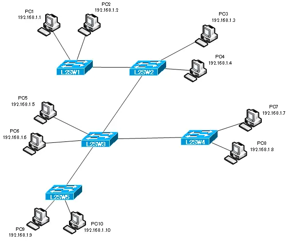
Consider the network diagram in the following figure.

The figure shows an example of a network with five Layer 2 switches, L2SW1 to L2SW5. PC1~PC10 are connected to these Layer 2 switches as hosts. Since the entire network is one, the IP addresses of the hosts are 192.168.1.1 to 192.168.1.10, which is the same network address.
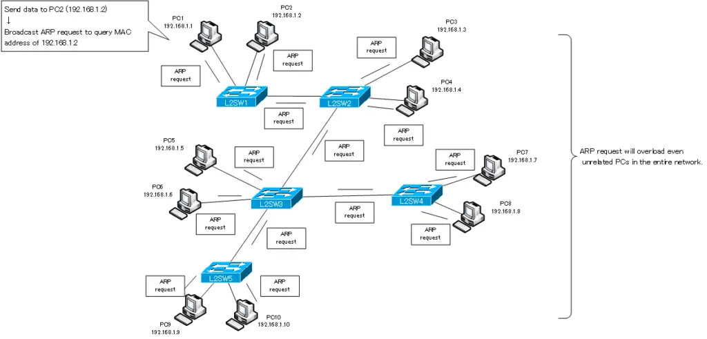
In order to send data from PC1 to PC2, which is connected to the same L2SW1, the MAC address of PC2 is required. When PC1 tries to send data to PC2’s IP address 192.168.1.2, it will automatically send an ARP request. PC1 queries the MAC address of 192.168.1.2 by ARP request. The ARP request sent from PC1 will be flooded to the entire network because it is a broadcast. This ARP request is only to query the MAC address of PC2, but it is a load on the entire network. And the broadcast frame also loads unrelated PCs other than the PC2 to be queried.
The data size of each ARP request itself is not large, and the processing load on unrelated PCs is not significant. However, when they pile up, it will be hard to ignore.

In addition to ARP requests, there are many other communications that use broadcast, such as DHCP. In addition to broadcast, multicast and Unknown unicast frames are also flooded. Thus, if there is only one network, the effect of flooding such as broadcast frames will increase. Therefore, we divide the network.
The mechanism of dividing a network with VLAN is explained in the following article.
VLAN(Virtual LAN)
- The need to divide the network
- Details of dividing the network
- VLAN Overview
- VLAN behavior
- Access port : Port assigned to only one VLAN
- Trunk port : Port assigned to multiple VLANs
- Summary of Trunk Protocols – IEEE802.1Q and ISL
- Native VLAN
- Specific example of native VLAN mismatch
- Cisco DTP
- Cisco Configuring and Verifying VLAN
- Cisco VLAN Detailed Configuration Example
- Notes on deleting VLANs
- Voice VLAN – VLAN for connecting IP phones
- VTP :Synchronize VLAN configuration
- VTP pruning – Stopping unnecessary flooding of trunk links
- Configuring and Verifying Cisco VTP
- Inter VLAN routing overview
- Inter-VLAN routing by router
- Inter-VLAN routing by Layer 3 switch
- Configuring and Verifying Inter-VLAN Routing by Cisco Router
- Cisco Configuring Inter-VLAN routing by Layer3 switch : SVI/routed port
- Cisco Layer3 Switch Basic Configuration Example
- Summary of Layer 3 Switch Port Concepts – Access Port/Trunk Port/SVI/Routed Port
- LAN Design pattern : 2-tier and 3-tier
