目次
概要
MPLS-VPNのバックボーンとなるMPLSネットワークの設定ミスについて、切り分けと修正を行います。
ネットワーク構成
下記のネットワーク構成で、MPLS-VPNを通じてR4とR5間の通信ができるようにしたいと考えています。
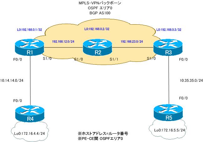
ルータの役割は、次の通りです。
PEルータ:R1、R3
Pルータ :R2
CEルータ:R4、R5
PEルータであるR1、R3ではともにVRFとして次のように定義します。
VRF名:VPN
RD:100:100
Import RT:100:100
Export RT:100:100
設定概要
各ルータで行われているMPLS-VPNでの通信に関連する設定は次の通りです。
R1
ip vrf VPN
 rd 100:100
 route-target export 100:100
 route-target import 100:100
!
interface Loopback0
 ip address 192.168.0.1 255.255.255.255
!
interface FastEthernet0/0
 ip vrf forwarding VPN
 ip address 10.14.14.1 255.255.255.0
!
interface Serial1/0
 ip address 192.168.12.1 255.255.255.0
 encapsulation ppp
 mpls ip
 no peer neighbor-route
!
router ospf 14 vrf VPN
 log-adjacency-changes
 redistribute bgp 100 subnets
 network 10.14.14.1 0.0.0.0 area 0
!
router ospf 1
 log-adjacency-changes
 network 192.168.0.0 0.0.255.255 area 0
!
router bgp 100
 no synchronization
 bgp log-neighbor-changes
 neighbor 192.168.0.3 remote-as 100
 neighbor 192.168.0.3 update-source Loopback0
 no auto-summary
 !
 address-family vpnv4
  neighbor 192.168.0.3 activate
  neighbor 192.168.0.3 send-community extended
 exit-address-family
 !
 address-family ipv4 vrf VPN
  redistribute ospf 14 vrf VPN
  no synchronization
 exit-address-family
R2
interface Loopback0
 ip address 192.168.0.2 255.255.255.255
!
interface Serial1/0
 ip address 192.168.12.2 255.255.255.0
 encapsulation ppp
 no peer neighbor-route
!
interface Serial1/1
 ip address 192.168.23.2 255.255.255.0
 encapsulation ppp
 mpls ip
 no peer neighbor-route
!
router ospf 1
 log-adjacency-changes
 network 192.168.0.0 0.0.255.255 area 0
R3
ip vrf VPN
 rd 100:100
 route-target export 100:100
 route-target import 100:100
!
interface Loopback0
 ip address 192.168.0.3 255.255.255.255
!
interface FastEthernet0/0
 ip vrf forwarding VPN
 ip address 10.35.35.3 255.255.255.0
 duplex auto
 speed auto
!
interface Serial1/0
 ip address 192.168.23.3 255.255.255.0
 encapsulation ppp
 mpls ip
 no peer neighbor-route
!
router ospf 35 vrf VPN
 log-adjacency-changes
 redistribute bgp 100 subnets
 network 10.35.35.3 0.0.0.0 area 0
!
router ospf 1
 log-adjacency-changes
 network 192.168.0.0 0.0.255.255 area 0
!
router bgp 100
 no synchronization
 bgp log-neighbor-changes
 neighbor 192.168.0.1 remote-as 100
 neighbor 192.168.0.1 update-source Loopback0
 no auto-summary
 !
 address-family vpnv4
  neighbor 192.168.0.1 activate
  neighbor 192.168.0.1 send-community extended
 exit-address-family
 !
 address-family ipv4 vrf VPN
  redistribute ospf 35 vrf VPN
  no synchronization
 exit-address-family
R4
interface Loopback0
 ip address 172.16.4.4 255.255.255.0
 ip ospf network point-to-point
!
interface FastEthernet0/0
 ip address 10.14.14.4 255.255.255.0
!
router ospf 1
 log-adjacency-changes
 network 10.14.14.4 0.0.0.0 area 0
 network 172.16.4.4 0.0.0.0 area 0
R5
interface Loopback0
 ip address 172.16.5.5 255.255.255.0
 ip ospf network point-to-point
!
interface FastEthernet0/0
 ip address 10.35.35.5 255.255.255.0
!
router ospf 1
 log-adjacency-changes
 network 10.35.35.5 0.0.0.0 area 0
 network 172.16.5.5 0.0.0.0 area 0
トラブルの症状
R4、R5のルーティングテーブルを見ると、お互いのルートを確認できます。
R4 show ip route
R4#show ip route
~省略~

Gateway of last resort is not set

     172.16.0.0/24 is subnetted, 2 subnets
C       172.16.4.0 is directly connected, Loopback0
O E2    172.16.5.0 [110/2] via 10.14.14.1, 00:20:00, FastEthernet0/0
     10.0.0.0/24 is subnetted, 2 subnets
O E2    10.35.35.0 [110/1] via 10.14.14.1, 00:20:00, FastEthernet0/0
C       10.14.14.0 is directly connected, FastEthernet0/0
R5 show ip route
R5#show ip route
~省略~

Gateway of last resort is not set

     172.16.0.0/24 is subnetted, 2 subnets
O E2    172.16.4.0 [110/2] via 10.35.35.3, 00:23:01, FastEthernet0/0
C       172.16.5.0 is directly connected, Loopback0
     10.0.0.0/24 is subnetted, 2 subnets
C       10.35.35.0 is directly connected, FastEthernet0/0
O E2    10.14.14.0 [110/1] via 10.35.35.3, 00:23:01, FastEthernet0/0
ところが、実際には通信ができません。R4から172.16.5.5へPingすると失敗します。
R4から172.16.5.5へPing
R4#ping 172.16.5.5 source loopback 0

Type escape sequence to abort.
Sending 5, 100-byte ICMP Echos to 172.16.5.5, timeout is 2 seconds:
Packet sent with a source address of 172.16.4.4
.....
Success rate is 0 percent (0/5)
CEルータであるR4、R5でお互いのルートが確認できているので、R4とR5には設定ミスがないことが明らかです。そこで、MPLS-VPNバックボーンを構成するR1、R2、R3でそれぞれ次のshowコマンドで原因の切り分けを行いました。
R1
show mpls interface
show mpls ldp neighbor
show ip bgp summary
show ip bgp vpnv4 all
show ip route vrf VPN
show ip cef vrf VPN 172.16.5.0
R2
show mpls interface
show mpls ldp neighbor
show mpls forwarding-table
R3
show mpls interface
show mpls ldp neighbor
show ip bgp summary
show ip bgp vpnv4 all
show ip route vrf VPN
show ip cef vrf VPN 172.16.4.0
R1 showコマンドの結果
R1#show mpls interface
Interface              IP            Tunnel   Operational
Serial1/0              Yes (ldp)     No       Yes
R1#show mpls ldp neighbor

R1#show ip bgp summary
BGP router identifier 192.168.0.1, local AS number 100
BGP table version is 1, main routing table version 1

Neighbor        V    AS MsgRcvd MsgSent   TblVer  InQ OutQ Up/Down  State/PfxRcd
192.168.0.3     4   100      43      43        1    0    0 00:33:52        0
R1#show ip bgp vpnv4 all
BGP table version is 9, local router ID is 192.168.0.1
Status codes: s suppressed, d damped, h history, * valid, > best, i - internal,
              r RIB-failure, S Stale
Origin codes: i - IGP, e - EGP, ? - incomplete

   Network          Next Hop            Metric LocPrf Weight Path
Route Distinguisher: 100:100 (default for vrf VPN)
*> 10.14.14.0/24    0.0.0.0                  0         32768 ?
*>i10.35.35.0/24    192.168.0.3              0    100      0 ?
*> 172.16.4.0/24    10.14.14.4               2         32768 ?
*>i172.16.5.0/24    192.168.0.3              2    100      0 ?
R1#show ip route vrf VPN

Routing Table: VPN
Codes: C - connected, S - static, R - RIP, M - mobile, B - BGP
       D - EIGRP, EX - EIGRP external, O - OSPF, IA - OSPF inter area
       N1 - OSPF NSSA external type 1, N2 - OSPF NSSA external type 2
       E1 - OSPF external type 1, E2 - OSPF external type 2
       i - IS-IS, su - IS-IS summary, L1 - IS-IS level-1, L2 - IS-IS level-2
       ia - IS-IS inter area, * - candidate default, U - per-user static route
       o - ODR, P - periodic downloaded static route

Gateway of last resort is not set

     172.16.0.0/24 is subnetted, 2 subnets
O       172.16.4.0 [110/2] via 10.14.14.4, 00:35:16, FastEthernet0/0
B       172.16.5.0 [200/2] via 192.168.0.3, 00:33:31
     10.0.0.0/24 is subnetted, 2 subnets
B       10.35.35.0 [200/0] via 192.168.0.3, 00:33:31
C       10.14.14.0 is directly connected, FastEthernet0/0
R1#show ip cef vrf VPN 172.16.5.0
172.16.5.0/24, version 14, epoch 0, cached adjacency to Serial1/0
0 packets, 0 bytes
  tag information set
    local tag: VPN-route-head
    fast tag rewrite with
        Recursive rewrite via 192.168.0.3/32, tags imposed {21}
  via 192.168.0.3, 0 dependencies, recursive
    next hop 192.168.12.2, Serial1/0 via 192.168.0.3/32
    valid cached adjacency
    tag rewrite with
        Recursive rewrite via 192.168.0.3/32, tags imposed {21}
R2 showコマンドの結果
R2#show mpls interface
Interface              IP            Tunnel   Operational
Serial1/1              Yes (ldp)     No       Yes
R2#show mpls ldp neighbor
    Peer LDP Ident: 192.168.0.3:0; Local LDP Ident 192.168.0.2:0
        TCP connection: 192.168.0.3.48691 - 192.168.0.2.646
        State: Oper; Msgs sent/rcvd: 89/90; Downstream
        Up time: 01:12:09
        LDP discovery sources:
          Serial1/1, Src IP addr: 192.168.23.3
        Addresses bound to peer LDP Ident:
          192.168.23.3    192.168.0.3
R2#show mpls forwarding-table
Local  Outgoing    Prefix            Bytes tag  Outgoing   Next Hop
tag    tag or VC   or Tunnel Id      switched   interface
16     Untagged    192.168.0.1/32    3317       Se1/0      point2point
17     Pop tag     192.168.0.3/32    2809       Se1/1      point2point
R3 showコマンドの結果
R3#show mpls interface
Interface              IP            Tunnel   Operational
Serial1/0              Yes (ldp)     No       Yes
R3#show mpls ldp neighbor
    Peer LDP Ident: 192.168.0.2:0; Local LDP Ident 192.168.0.3:0
        TCP connection: 192.168.0.2.646 - 192.168.0.3.48691
        State: Oper; Msgs sent/rcvd: 90/90; Downstream
        Up time: 01:12:51
        LDP discovery sources:
          Serial1/0, Src IP addr: 192.168.23.2
        Addresses bound to peer LDP Ident:
          192.168.12.2    192.168.23.2    192.168.0.2
R3#show ip bgp summary
BGP router identifier 192.168.0.3, local AS number 100
BGP table version is 1, main routing table version 1

Neighbor        V    AS MsgRcvd MsgSent   TblVer  InQ OutQ Up/Down  State/PfxRcd
192.168.0.1     4   100      45      45        1    0    0 00:35:25        0
R3#show ip bgp vpnv4 all
BGP table version is 9, local router ID is 192.168.0.3
Status codes: s suppressed, d damped, h history, * valid, > best, i - internal,
              r RIB-failure, S Stale
Origin codes: i - IGP, e - EGP, ? - incomplete

   Network          Next Hop            Metric LocPrf Weight Path
Route Distinguisher: 100:100 (default for vrf VPN)
*>i10.14.14.0/24    192.168.0.1              0    100      0 ?
*> 10.35.35.0/24    0.0.0.0                  0         32768 ?
*>i172.16.4.0/24    192.168.0.1              2    100      0 ?
*> 172.16.5.0/24    10.35.35.5               2         32768 ?
R3#show ip route vrf VPN

Routing Table: VPN
Codes: C - connected, S - static, R - RIP, M - mobile, B - BGP
       D - EIGRP, EX - EIGRP external, O - OSPF, IA - OSPF inter area
       N1 - OSPF NSSA external type 1, N2 - OSPF NSSA external type 2
       E1 - OSPF external type 1, E2 - OSPF external type 2
       i - IS-IS, su - IS-IS summary, L1 - IS-IS level-1, L2 - IS-IS level-2
       ia - IS-IS inter area, * - candidate default, U - per-user static route
       o - ODR, P - periodic downloaded static route

Gateway of last resort is not set

     172.16.0.0/24 is subnetted, 2 subnets
B       172.16.4.0 [200/2] via 192.168.0.1, 00:35:09
O       172.16.5.0 [110/2] via 10.35.35.5, 00:36:41, FastEthernet0/0
     10.0.0.0/24 is subnetted, 2 subnets
C       10.35.35.0 is directly connected, FastEthernet0/0
B       10.14.14.0 [200/0] via 192.168.0.1, 00:35:09
R3#show ip cef vrf VPN 172.16.4.0
172.16.4.0/24, version 14, epoch 0, cached adjacency to Serial1/0
0 packets, 0 bytes
  tag information set
    local tag: VPN-route-head
    fast tag rewrite with Se1/0, point2point, tags imposed: {16 22}
  via 192.168.0.1, 0 dependencies, recursive
    next hop 192.168.23.2, Serial1/0 via 192.168.0.1/32
    valid cached adjacency
    tag rewrite with Se1/0, point2point, tags imposed: {16 22}
R1~R3のshowコマンドによって設定ミスがわかったので修正すると、正常にMPLS-VPNを通じてR4-R5間の通信ができるようになりました。
問題
- R4、R5ではお互いのルートを学習できているのになぜ通信できないのですか?
- MPLS-VPN経由でR4-R5間の通信ができるようにするためには、どのように設定を修正すればよいですか?
解答
R4、R5ではお互いのルートを学習できているのになぜ通信できないのですか?
MPLS-VPNに接続しているユーザサイト内のルート(VPNルート)は、MP-BGPでMPLSバックボーン内のPE間で学習する。MPLSバックボーン内でIPルーティングできていれば、MP-BGPでのVPNルートの交換とVPNルートに対するラベル割り当てが可能。
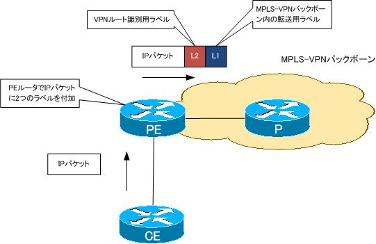
ユーザサイト間のIPパケットをMPLSバックボーン内でスイッチングするためには、PEルータでVPNルートのラベルとMPLSバックボーン内での転送用のラベルを付加する。転送用のラベルはMPLSバックボーン内でLDPによって割り当てと配布を行う。転送用のラベルが正しくなければ、ユーザサイト間のIPパケットはMPLSバックボーン内で破棄される。
R1とR2の間でLDPネイバーが確立されていないので、R1はR3までのMPLSバックボーン内の転送用ラベルがなく、VPNルートのラベルのみを付加してR2へ転送する。R2では、VPNルートのラベルは認識できないのでパケットを破棄する。
MPLS-VPN経由でR4-R5間の通信ができるようにするためには、どのように設定を修正すればよいですか?
R2
interface serial1/0
 mpls ip
ワンポイント
- MPLS-VPNでは、ユーザサイト間のIPパケットに2つのラベルを付加する
解説
MPLS-VPNは、MPLSの用途として最も一般的なものでしょう。多くのIP-VPNサービスはMPLS-VPNによって実現しています。MPLS-VPNバックボーンに接続したユーザサイト間のIPパケットを転送するためにPEルータで次の2つのラベルを付加します。
- 1番目のラベル:MPLS-VPNバックボーン内の転送用ラベル
- 2番目のラベル:ユーザサイトのネットワーク(VPNルート)を識別するラベル
この2つのラベルは、それぞれ割り当てと配布の仕組みが異なっています。今回の設定ミスは、2つのラベルの割り当てと配布の仕組みがきちんとわかっているかどうかがポイントです。
PEルータは、R1とR3です。PEルータでCEルータから受信したIPパケットに付加するラベルを確認するには、show ip cefを見ます。R1のCEFテーブルを見ると、172.16.5.0/24に対するラベルが1つしかありません。
R1 show ip cef vrf VPN 172.16.5.0
R1#show ip cef vrf VPN 172.16.5.0
172.16.5.0/24, version 14, epoch 0, cached adjacency to Serial1/0
0 packets, 0 bytes
  tag information set
    local tag: VPN-route-head
    fast tag rewrite with
        Recursive rewrite via 192.168.0.3/32, tags imposed {21}
  via 192.168.0.3, 0 dependencies, recursive
    next hop 192.168.12.2, Serial1/0 via 192.168.0.3/32
    valid cached adjacency
    tag rewrite with
        Recursive rewrite via 192.168.0.3/32, tags imposed {21}
MP-BGPのネイバーは確立されていてルートの交換がきちんとできているので、「21」というラベルは、MP-BGPで割り当てと配布を行っているVPNルートのラベルです。つまり、R1はMPLS-VPNバックボーン内を転送するためのラベルを持っていません。ということは、MPLS-VPNバックボーン内のLDPに問題があることがわかります。そこで、LDPに関するshowコマンドを確認すると、R2 S1/0でLDPが有効化されていません。そのため、R1-R2間でLDPネイバーを確立できていません。これがR1でMPLS-VPNバックボーン内転送用ラベルを学習できていない原因です。
R2 showコマンドの結果(LDP)
R2#show mpls interface
Interface              IP            Tunnel   Operational
Serial1/1              Yes (ldp)     No       Yes
R2#show mpls ldp neighbor
    Peer LDP Ident: 192.168.0.3:0; Local LDP Ident 192.168.0.2:0
        TCP connection: 192.168.0.3.48691 - 192.168.0.2.646
        State: Oper; Msgs sent/rcvd: 89/90; Downstream
        Up time: 01:12:09
        LDP discovery sources:
          Serial1/1, Src IP addr: 192.168.23.3
        Addresses bound to peer LDP Ident:
          192.168.23.3    192.168.0.3
これを解決するためには、R2 S1/0でLDPを有効化して、R1がMPLS-VPNバックボーン内転送用ラベルを学習できるようにします。
R2 S1/0でLDPを有効化
interface serial1/0
 mpls ip
R2 S1/0でLDPを有効化したあと、R1でLDPネイバーとCEFテーブルを確認すると、次のようになります。
R1 show mpls ldp neighbor/show ip cef vrf VPN 172.16.5.0
R1#show mpls ldp neighbor
    Peer LDP Ident: 192.168.0.2:0; Local LDP Ident 192.168.0.1:0
        TCP connection: 192.168.0.2.48975 - 192.168.0.1.646
        State: Oper; Msgs sent/rcvd: 12/12; Downstream
        Up time: 00:04:12
        LDP discovery sources:
          Serial1/0, Src IP addr: 192.168.12.2
        Addresses bound to peer LDP Ident:
          192.168.12.2    192.168.23.2    192.168.0.2
R1#show ip cef vrf VPN 172.16.5.0
172.16.5.0/24, version 17, epoch 0, cached adjacency to Serial1/0
0 packets, 0 bytes
  tag information set
    local tag: VPN-route-head
    fast tag rewrite with Se1/0, point2point, tags imposed: {17 20}
  via 192.168.0.3, 0 dependencies, recursive
    next hop 192.168.12.2, Serial1/0 via 192.168.0.3/32
    valid cached adjacency
    tag rewrite with Se1/0, point2point, tags imposed: {17 20}
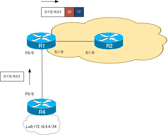
これを見ると、R1-R2間でLDPネイバーを確立できていて、172.16.5.0/24に対して転送用とVPNルート識別用の2つのラベル情報を持っていることがわかります。そして、R4からR5にPingを実行すると、成功します。
R4から172.16.5.5へPing
R4#ping 172.16.5.5 source 172.16.4.4

Type escape sequence to abort.
Sending 5, 100-byte ICMP Echos to 172.16.5.5, timeout is 2 seconds:
Packet sent with a source address of 172.16.4.4
!!!!!
Success rate is 100 percent (5/5), round-trip min/avg/max = 20/36/64 ms
以上のように、2つのラベルをどのような仕組みで割り当てて配布するかについて、きちんと理解しておけば、どこでどのようなshowコマンドで確認すればよいかが明確になります。
ついでに、R4からR5へPingする場合のパケットの転送の様子を追ってみましょう。R4からR5あてのPingパケットはR1で2つのラベルを付加して、MPLS-VPNバックボーン内のR2へ転送します。付加するラベルは、先ほども載せているshow ip cef vrf VPN 172.16.5.0で確認できるように、17と20です。
R1 show ip cef vrf VPN 172.16.5.0
R1#show ip cef vrf VPN 172.16.5.0
172.16.5.0/24, version 17, epoch 0, cached adjacency to Serial1/0
0 packets, 0 bytes
  tag information set
    local tag: VPN-route-head
    fast tag rewrite with Se1/0, point2point, tags imposed: {17 20}
  via 192.168.0.3, 0 dependencies, recursive
    next hop 192.168.12.2, Serial1/0 via 192.168.0.3/32
    valid cached adjacency
    tag rewrite with Se1/0, point2point, tags imposed: {17 20}
R2では、ラベル付きのパケットを転送するためにshow mpls forwarding-tableを見ます。
R2 show mpls forwarding-table
R2#show mpls forwarding-table
Local  Outgoing    Prefix            Bytes tag  Outgoing   Next Hop
tag    tag or VC   or Tunnel Id      switched   interface
16     Pop tag     192.168.0.1/32    2562       Se1/0      point2point
17     Pop tag     192.168.0.3/32    2222       Se1/1      point2point
これを見ると、ラベル17が付いているパケットはそのラベルを外して、Se1/1、つまりR3へ転送することがわかります。
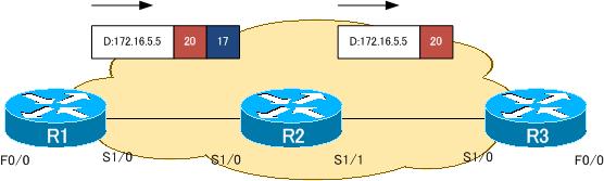
R3に転送されるパケットにはまだ1つラベルが付いています。ラベル付きパケットなので、show mpls forwarding-tableによってパケットを転送します。
R3 show mpls forwarding-table
R3#show mpls forwarding-table
Local  Outgoing    Prefix            Bytes tag  Outgoing   Next Hop
tag    tag or VC   or Tunnel Id      switched   interface
16     16          192.168.0.1/32    0          Se1/0      point2point
17     Pop tag     192.168.0.2/32    0          Se1/0      point2point
18     Pop tag     192.168.12.0/24   0          Se1/0      point2point
19     Aggregate   10.35.35.0/24[V]  0
20     Untagged    172.16.5.0/24[V]  570        Fa0/0      10.35.35.5
ラベル20が付いているパケットは、「Untagged」します。「Untagged」はすべてのラベルを取り除いてIPパケットに戻すという意味です。R3はラベルをすべて外して、Fa0/0、つまりR5へ転送します。
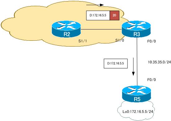
あとは、もう省略しますが、R5からの返事も同じようにMPLS-VPNバックボーンを通じて転送されることになります。
動画解説
MPLS/MPLS-VPN
- MPLSラベルスイッチングの設定と確認コマンド[Cisco]
- MPLSによるラベルスイッチングの設定例 [Cisco]
- MPLSによるトランジットASの構成
- MPLS 設定ミスの切り分けと修正 Part1
- MPLS 設定ミスの切り分けと修正 Part2
- MPLS-VPNの設定例 フルメッシュ(Any-to-Any)
- MPLS-VPNの設定例 エクストラネットVPN
- MPLS-VPNの設定例 セントラルサービスVPN
- MPLS-VPNの設定例 ハブ&スポークVPN
- OSPF Sham-linkの概要
- OSPF Sham-linkの設定
- MPLS-VPN 設定ミスの切り分けと修正 Part1
- MPLS-VPN 設定ミスの切り分けと修正 Part2
- MPLS-VPN 設定ミスの切り分けと修正 Part3
- MPLS-VPN 設定ミスの切り分けと修正 Part4
- MPLS-VPN 設定ミスの切り分けと修正 Part5
- MPLS-VPN 設定ミスの切り分けと修正 Part6