目次
概要
MPLS-VPNでは、PE-CE間のVRFのルーティングの設定が必要です。PE-CE間のVRFルーティングのBGPおよびスタティックルートについて、設定ミスの切り分けと修正を行います。
ネットワーク構成
下記のネットワーク構成で、MPLS-VPNを通じてR4とR5間の通信ができるようにしたいと考えています。
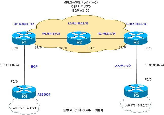
ルータの役割は、次の通りです。
PEルータ:R1、R3
Pルータ :R2
CEルータ:R4、R5
PEルータであるR1、R3ではともにVRFとして次のように定義しています。
VRF名:VPN
RD:100:100
Import RT:100:100
Export RT:100:100
また、PE-CE間のルーティングは次の通りです。
R1-R4:BGP
R3-R5:スタティック
設定概要
各ルータで行われているMPLS-VPNでの通信に関連する設定は次の通りです。
R1
ip vrf VPN
 rd 100:100
 route-target export 100:100
 route-target import 100:100
!
interface Loopback0
 ip address 192.168.0.1 255.255.255.255
!
interface FastEthernet0/0
 ip vrf forwarding VPN
 ip address 10.14.14.1 255.255.255.0
!
interface Serial1/0
 ip address 192.168.12.1 255.255.255.0
 encapsulation ppp
 mpls ip
 no peer neighbor-route
!
router ospf 1
 log-adjacency-changes
 network 192.168.0.0 0.0.255.255 area 0
!
router bgp 100
 no synchronization
 bgp log-neighbor-changes
 neighbor 192.168.0.3 remote-as 100
 neighbor 192.168.0.3 update-source Loopback0
 no auto-summary
 !
 address-family vpnv4
  neighbor 192.168.0.3 activate
  neighbor 192.168.0.3 send-community extended
 exit-address-family
 !
 address-family ipv4 vrf VPN
  redistribute eigrp 100
  neighbor 10.14.14.4 remote-as 65004
  no neighbor 10.14.14.4 activate
  no synchronization
 exit-address-family
R2
interface Loopback0
 ip address 192.168.0.2 255.255.255.255
!
interface Serial1/0
 ip address 192.168.12.2 255.255.255.0
 encapsulation ppp
 mpls ip
 no peer neighbor-route
!
interface Serial1/1
 ip address 192.168.23.2 255.255.255.0
 encapsulation ppp
 mpls ip
 no peer neighbor-route
!
router ospf 1
 log-adjacency-changes
 network 192.168.0.0 0.0.255.255 area 0
R3
ip vrf VPN
 rd 100:100
 route-target export 100:100
 route-target import 100:100
!
interface Loopback0
 ip address 192.168.0.3 255.255.255.255
!
interface FastEthernet0/0
 ip vrf forwarding VPN
 ip address 10.35.35.3 255.255.255.0
 duplex auto
 speed auto
!
interface Serial1/0
 ip address 192.168.23.3 255.255.255.0
 encapsulation ppp
 mpls ip
 no peer neighbor-route
!
router ospf 1
 log-adjacency-changes
 network 192.168.0.0 0.0.255.255 area 0
!
router bgp 100
 no synchronization
 bgp log-neighbor-changes
 neighbor 192.168.0.1 remote-as 100
 neighbor 192.168.0.1 update-source Loopback0
 no auto-summary
 !
 address-family vpnv4
  neighbor 192.168.0.1 activate
  neighbor 192.168.0.1 send-community extended
 exit-address-family
 !
 address-family ipv4 vrf VPN
  redistribute static
  no synchronization
 exit-address-family
!
ip route 172.16.5.0 255.255.255.0 10.35.35.5
R4
interface Loopback0
 ip address 172.16.4.4 255.255.255.0
 ip ospf network point-to-point
!
interface FastEthernet0/0
 ip address 10.14.14.4 255.255.255.0
!
router bgp 65004
 no synchronization
 bgp log-neighbor-changes
 network 172.16.4.0 mask 255.255.255.0
 neighbor 10.14.14.1 remote-as 100
 no auto-summary
R5
interface Loopback0
 ip address 172.16.5.5 255.255.255.0
 ip ospf network point-to-point
!
interface FastEthernet0/0
 ip address 10.35.35.5 255.255.255.0
!
ip route 0.0.0.0 0.0.0.0 10.35.35.3
トラブルの症状
R4とR5間で通信ができません。R4およびR5のルーティングテーブルを見ると、次のようになっています。
R4 show ip route
R4#show ip route
~省略~

Gateway of last resort is not set

     172.16.0.0/24 is subnetted, 1 subnets
C       172.16.4.0 is directly connected, Loopback0
     10.0.0.0/24 is subnetted, 1 subnets
C       10.14.14.0 is directly connected, FastEthernet0/
R5 show ip route
R5#show ip route
~省略~

Gateway of last resort is 10.35.35.3 to network 0.0.0.0

     172.16.0.0/24 is subnetted, 1 subnets
C       172.16.5.0 is directly connected, Loopback0
     10.0.0.0/24 is subnetted, 1 subnets
C       10.35.35.0 is directly connected, FastEthernet0/0
S*   0.0.0.0/0 [1/0] via 10.35.35.3
R4-R5間の通信に必要なルート情報がルーティングテーブルに登録されていません。そのため、通信もできていません。
トラブルを解決するためにまずPE-CE間のルーティングについて確認しました。R1-R4間のBGPのルーティングを次のshowコマンドで確認しています。
R1
show ip protocols vrf VPN
show ip bgp vpnv4 vrf VPN summary
show ip bgp vpnv4 vrf VPN
R4
show ip protocols
show ip bgp summary
show ip bgp
R1 showコマンドの結果
R1#show ip protocols vrf VPN
Routing Protocol is "bgp 100"
  Outgoing update filter list for all interfaces is not set
  Incoming update filter list for all interfaces is not set
  IGP synchronization is disabled
  Automatic route summarization is disabled
  Maximum path: 1
  Routing Information Sources:
    Gateway         Distance      Last Update
    10.14.14.4            20      00:02:05
    192.168.0.3          200      00:15:15
  Distance: external 20 internal 200 local 200

R1#show ip bgp vpnv4 vrf VPN summary

R1#show ip bgp vpnv4 vrf VPN
R4 showコマンドの結果
R4#show ip protocols
Routing Protocol is "bgp 65004"
  Outgoing update filter list for all interfaces is not set
  Incoming update filter list for all interfaces is not set
  IGP synchronization is disabled
  Automatic route summarization is disabled
  Neighbor(s):
    Address          FiltIn FiltOut DistIn DistOut Weight RouteMap
    10.14.14.1
  Maximum path: 1
  Routing Information Sources:
    Gateway         Distance      Last Update
    10.14.14.1            20      00:15:11
  Distance: external 20 internal 200 local 200

R4#show ip bgp summary
BGP router identifier 172.16.4.4, local AS number 65004
BGP table version is 6, main routing table version 6
1 network entries using 117 bytes of memory
1 path entries using 52 bytes of memory
2/1 BGP path/bestpath attribute entries using 248 bytes of memory
0 BGP route-map cache entries using 0 bytes of memory
0 BGP filter-list cache entries using 0 bytes of memory
BGP using 417 total bytes of memory
BGP activity 3/2 prefixes, 3/2 paths, scan interval 60 secs

Neighbor        V    AS MsgRcvd MsgSent   TblVer  InQ OutQ Up/Down  State/PfxRcd
10.14.14.1      4   100      19      17        0    0    0 00:01:31 Active
R4#show ip bgp
BGP table version is 6, local router ID is 172.16.4.4
Status codes: s suppressed, d damped, h history, * valid, > best, i - internal,
              r RIB-failure, S Stale
Origin codes: i - IGP, e - EGP, ? - incomplete

   Network          Next Hop            Metric LocPrf Weight Path
*> 172.16.4.0/24    0.0.0.0                  0         32768 i
R3-R5間のスタティックのルーティングを次のshowコマンドで確認しています。
R3
show ip route vrf VPN
R5
show ip route
R3 showコマンドの結果
R3#show ip route vrf VPN

Routing Table: VPN
Codes: C - connected, S - static, R - RIP, M - mobile, B - BGP
       D - EIGRP, EX - EIGRP external, O - OSPF, IA - OSPF inter area
       N1 - OSPF NSSA external type 1, N2 - OSPF NSSA external type 2
       E1 - OSPF external type 1, E2 - OSPF external type 2
       i - IS-IS, su - IS-IS summary, L1 - IS-IS level-1, L2 - IS-IS level-2
       ia - IS-IS inter area, * - candidate default, U - per-user static route
       o - ODR, P - periodic downloaded static route

Gateway of last resort is not set

     10.0.0.0/24 is subnetted, 1 subnets
C       10.35.35.0 is directly connected, FastEthernet0/0
R5 showコマンドの結果
5#show ip route
Codes: C - connected, S - static, R - RIP, M - mobile, B - BGP
       D - EIGRP, EX - EIGRP external, O - OSPF, IA - OSPF inter area
       N1 - OSPF NSSA external type 1, N2 - OSPF NSSA external type 2
       E1 - OSPF external type 1, E2 - OSPF external type 2
       i - IS-IS, su - IS-IS summary, L1 - IS-IS level-1, L2 - IS-IS level-2
       ia - IS-IS inter area, * - candidate default, U - per-user static route
       o - ODR, P - periodic downloaded static route

Gateway of last resort is 10.35.35.3 to network 0.0.0.0

     172.16.0.0/24 is subnetted, 1 subnets
C       172.16.5.0 is directly connected, Loopback0
     10.0.0.0/24 is subnetted, 1 subnets
C       10.35.35.0 is directly connected, FastEthernet0/0
S*   0.0.0.0/0 [1/0] via 10.35.35.3
これらのshowコマンドによって、PE-CE間のルーティングがうまくできていないことがわかりました。設定ミスを修正すると、R4-R5間の通信が可能になりました。
問題
- PE-CE間のルーティングができていない理由はなんですか?
- MPLS-VPN経由でR4-R5間の通信ができるようにするためには、どのように設定を修正すればよいですか?
解答
PE-CE間のルーティングができていない理由はなんですか?
【R1-R4間】
R1で、VRF「VPN」のBGPネイバーとしてR4を指定しているが、activateされていないため、BGPネイバーを確立できていないから。
【R3-R5間】
R3のスタティックルートの設定がVRF「VPN」ではなく、グローバルルーティングテーブルでの設定になっているため
MPLS-VPN経由でR4-R5間の通信ができるようにするためには、どのように設定を修正すればよいですか?
R1
router bgp 100
 address-family ipv4 vrf VPN
  neighbor 10.14.14.4 activate
R3
no ip route 172.16.5.0 255.255.255.0 10.35.35.5
ip route vrf VPN 172.16.5.0 255.255.255.0 10.35.35.5
ワンポイント
- PE-CE間でBGPを利用するときは、該当するVRFの中でBGPネイバーの指定とactivateが必要
- PE-CE間でスタティックルートを利用するときは該当するVRFでスタティックルートを設定する
解説
PEルータであるR1とR3で接続しているCEルータのR4、R5のルートを正しく認識できていません。そのため、トラブルの原因はPEルータとCEルータのルーティングにあることが推測できます。R1-R4間のBGPとR3-R5間のスタティックのルーティングについてそれぞれ考えていきます。
【R1-R4間】
R1-R4間ではBGPを利用していますが、BGPネイバーを確立できていません。BGPネイバーを確認すると、R1では、次のように何も表示されていません。
R1 show ip bgp vpnv4 vrf VPN summary
R1#show ip bgp vpnv4 vrf VPN summary
R1でのBGPネイバーの設定を確認すると、address-family ipv4 vrf VPN の中でネイバーとしてR4を指定しています。しかし、activateされていないことがわかります。
R1 BGPネイバーの設定抜粋
router bgp 100
 address-family ipv4 vrf VPN
  redistribute eigrp 100
  neighbor 10.14.14.4 remote-as 65004
  no neighbor 10.14.14.4 activate
  no synchronization
 exit-address-family
PE-CE間でBGPを利用するときは、該当のVRFのaddress-familyでネイバーを指定してactivateしなければいけません。activateされていなければ、ネイバーを確立できません。当然、BGPでのルートの交換もできません。R1でR4に対するネイバーがactivateされていないことがトラブルの原因です。
トラブルを解決するために、R1で次のようにR4に対するBGPネイバーをactivateします。
R1 R4のactivate
router bgp 100
 address-family ipv4 vrf VPN
  neighbor 10.14.14.4 activate
R1でVRF「VPN」のBGPネイバーとしてR4をactivateすれば、BGPネイバーを確立し、BGPでルートを交換できるようになります。R1のVRF「VPN」のBGPネイバーとBGPテーブルは次のようになります。
R1 show ip bgp vpnv4 vrf VPN summary/show ip bgp vpnv4 all
R1#show ip bgp vpnv4 vrf VPN summary
BGP router identifier 192.168.0.1, local AS number 100
BGP table version is 2, main routing table version 2
1 network entries using 137 bytes of memory
1 path entries using 68 bytes of memory
3/1 BGP path/bestpath attribute entries using 372 bytes of memory
1 BGP AS-PATH entries using 24 bytes of memory
1 BGP extended community entries using 24 bytes of memory
0 BGP route-map cache entries using 0 bytes of memory
0 BGP filter-list cache entries using 0 bytes of memory
BGP using 625 total bytes of memory
BGP activity 1/0 prefixes, 1/0 paths, scan interval 15 secs

Neighbor        V    AS MsgRcvd MsgSent   TblVer  InQ OutQ Up/Down  State/PfxRcd
10.14.14.4      4 65004       5       4        2    0    0 00:00:29        1
R1#show ip bgp vpnv4 all
BGP table version is 2, local router ID is 192.168.0.1
Status codes: s suppressed, d damped, h history, * valid, > best, i - internal,
              r RIB-failure, S Stale
Origin codes: i - IGP, e - EGP, ? - incomplete

   Network          Next Hop            Metric LocPrf Weight Path
Route Distinguisher: 100:100 (default for vrf VPN)
*> 172.16.4.0/24    10.14.14.4               0             0 65004 i
これでR1-R4間のBGPのルーティングを正常に行うことができます。
【R3-R5間】
R3-R5間では、スタティックルートでルーティングを行っています。PEルータであるR3にはVRFのルーティングテーブルにR5のネットワークのルートをスタティックルートで設定します。ところが、R3でVRF「VPN」のルーティングテーブルを見てもR5の172.16.5.0/24のルートが存在しません。
R3 show ip route vrf VPN
R3#show ip route vrf VPN

Routing Table: VPN
Codes: C - connected, S - static, R - RIP, M - mobile, B - BGP
       D - EIGRP, EX - EIGRP external, O - OSPF, IA - OSPF inter area
       N1 - OSPF NSSA external type 1, N2 - OSPF NSSA external type 2
       E1 - OSPF external type 1, E2 - OSPF external type 2
       i - IS-IS, su - IS-IS summary, L1 - IS-IS level-1, L2 - IS-IS level-2
       ia - IS-IS inter area, * - candidate default, U - per-user static route
       o - ODR, P - periodic downloaded static route

Gateway of last resort is not set

     10.0.0.0/24 is subnetted, 1 subnets
C       10.35.35.0 is directly connected, FastEthernet0/0
そのため、R3でスタティックルートの設定が間違っていることが考えられます。そこで、R3のスタティックルートの設定を確認すると、VRFの指定が抜けています。VRFを指定しなければ、グローバルのルーティングテーブルにスタティックルートが登録されてしまいます。スタティックルートの設定でVRFの指定が抜けているのがトラブルの原因です。
トラブルを解決するために、R3でスタティックルートの設定を修正します。
R3
no ip route 172.16.5.0 255.255.255.0 10.35.35.5
ip route vrf VPN 172.16.5.0 255.255.255.0 10.35.35.5
その後、R3でVRF「VPN」のルーティングテーブルを確認すると、正常にR5の172.16.5.0/24のルートが登録されることがわかります。
R3 show ip route vrf VPN
R3#show ip route vrf VPN

Routing Table: VPN
Codes: C - connected, S - static, R - RIP, M - mobile, B - BGP
       D - EIGRP, EX - EIGRP external, O - OSPF, IA - OSPF inter area
       N1 - OSPF NSSA external type 1, N2 - OSPF NSSA external type 2
       E1 - OSPF external type 1, E2 - OSPF external type 2
       i - IS-IS, su - IS-IS summary, L1 - IS-IS level-1, L2 - IS-IS level-2
       ia - IS-IS inter area, * - candidate default, U - per-user static route
       o - ODR, P - periodic downloaded static route

Gateway of last resort is not set

     172.16.0.0/24 is subnetted, 2 subnets
B       172.16.4.0 [200/0] via 192.168.0.1, 00:18:09
S       172.16.5.0 [1/0] via 10.35.35.5
     10.0.0.0/24 is subnetted, 1 subnets
C       10.35.35.0 is directly connected, FastEthernet0/0
これでR3-R5間のスタティックのルーティングを正常に行うことができます。
R1-R3間、R3-R5間のルーティングを正常に行うことができるようになったので、R4とR5の通信も可能です。R4からR5にPingすると、次のように成功します。
R4 R5へPing
R4#ping 172.16.5.5 source 172.16.4.4

Type escape sequence to abort.
Sending 5, 100-byte ICMP Echos to 172.16.5.5, timeout is 2 seconds:
Packet sent with a source address of 172.16.4.4
!!!!!
Success rate is 100 percent (5/5), round-trip min/avg/max = 16/34/68 ms

MPLS/MPLS-VPN
- MPLSラベルスイッチングの設定と確認コマンド[Cisco]
- MPLSによるラベルスイッチングの設定例 [Cisco]
- MPLSによるトランジットASの構成
- MPLS 設定ミスの切り分けと修正 Part1
- MPLS 設定ミスの切り分けと修正 Part2
- MPLS-VPNの設定例 フルメッシュ(Any-to-Any)
- MPLS-VPNの設定例 エクストラネットVPN
- MPLS-VPNの設定例 セントラルサービスVPN
- MPLS-VPNの設定例 ハブ&スポークVPN
- OSPF Sham-linkの概要
- OSPF Sham-linkの設定
- MPLS-VPN 設定ミスの切り分けと修正 Part1
- MPLS-VPN 設定ミスの切り分けと修正 Part2
- MPLS-VPN 設定ミスの切り分けと修正 Part3
- MPLS-VPN 設定ミスの切り分けと修正 Part4
- MPLS-VPN 設定ミスの切り分けと修正 Part5
- MPLS-VPN 設定ミスの切り分けと修正 Part6