ネットワーク構成
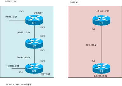
図 VRFとtunnelインタフェース
設定条件
- R1とR3でVRF「TEST」を作成してください。RDは100:100とします。
- ネットワーク構成にしたがって、R1とR3でVRFをインタフェースに割り当ててIPアドレスを設定してください。
- R1とR3でスタティックトンネルTunnel0を作成してください。カプセル化するIPアドレスはE0/0を利用します。
- Tunnel0経由のIPパケットはIPSecで保護してください。
- R1(VRF TEST)、R2、R3(VRF TEST)でOSPFのルーティングを行います。ルータIDは「x.x.x.x」(x=ルータ番号)とします。
- R1、R3でEIGRP AS1のルーティングを行います。
初期設定
以下の設定は設定済みです。
- ホスト名
- IPアドレス
R1 Lo0、R3 Lo0 - R2の設定は完了
設定と確認
Step1:VRFの作成とインタフェースの割り当て
R1とR3でVRF「TEST」を作成します。そして、E0/0、E0/1をVRF「TEST」に割り当ててIPアドレスを設定します。
R1
------------------------------
ip vrf TEST
rd 100:100
!
interface Ethernet0/0
ip vrf forwarding TEST
ip address 192.168.12.1 255.255.255.0
!
interface Ethernet0/1
ip vrf forwarding TEST
ip address 192.168.1.1 255.255.255.0
------------------------------
R3
------------------------------
ip vrf TEST
rd 100:100
!
interface Ethernet0/0
ip vrf forwarding TEST
ip address 192.168.23.3 255.255.255.0
!
interface Ethernet0/1
ip vrf forwarding TEST
ip address 192.168.3.3 255.255.255.0
------------------------------
Step2:VRF TEST OSPFの設定
R1、R3のVRF「TEST」でOSPFによるルーティングを行います。ルータIDとして、「x.x.x.x」(x=1 or 3)を設定して、E0/0、E0/1でOSPFを有効化します。
R1
------------------------------
router ospf 1 vrf TEST
router-id 1.1.1.1
log-adjacency-changes
network 192.168.0.0 0.0.255.255 area 0
------------------------------
R3
------------------------------
router ospf 1 vrf TEST
router-id 3.3.3.3
log-adjacency-changes
network 192.168.0.0 0.0.255.255 area 0
------------------------------
Step3:tunnelインタフェースの作成
R1、R3でTunnel0インタフェースを作成します。tunnel destinationとtunnel sourceはE0/0のIPアドレスを利用します。また、Tunnel0インタフェースには、10.13.13.x/24(x=1 or 3)を設定します。
R1
------------------------------
interface Tunnel0
ip address 10.13.13.1 255.255.255.0
tunnel source Ethernet0/0
tunnel destination 192.168.23.3
------------------------------
R3
------------------------------
interface Tunnel0
ip address 10.13.13.3 255.255.255.0
tunnel source Ethernet0/0
tunnel destination 192.168.12.1
------------------------------
Step4:tunnelインタフェースの確認
Step3で設定したR1、R3のTunnel0インタフェースの状態を確認します。
R1
------------------------------
R1#show interfaces tunnel 0
Tunnel0 is up, line protocol is down
Hardware is Tunnel
Internet address is 10.13.13.1/24
MTU 1514 bytes, BW 9 Kbit/sec, DLY 500000 usec,
reliability 255/255, txload 1/255, rxload 1/255
Encapsulation TUNNEL, loopback not set
Keepalive not set
Tunnel source 192.168.12.1 (Ethernet0/0), destination 192.168.23.3
Tunnel protocol/transport GRE/IP
Key disabled, sequencing disabled
Checksumming of packets disabled
Tunnel TTL 255
~省略~
------------------------------
R3
------------------------------
R3#show interfaces tunnel 0
Tunnel0 is up, line protocol is down
Hardware is Tunnel
Internet address is 10.13.13.3/24
MTU 1514 bytes, BW 9 Kbit/sec, DLY 500000 usec,
reliability 255/255, txload 1/255, rxload 1/255
Encapsulation TUNNEL, loopback not set
Keepalive not set
Tunnel source 192.168.23.3 (Ethernet0/0), destination 192.168.12.1
Tunnel protocol/transport GRE/IP
Key disabled, sequencing disabled
Checksumming of packets disabled
Tunnel TTL 255
~省略=
------------------------------
Tunnel0インタフェースはup/downの状態です。これはtunnel destinationのIPアドレスに到達できないためです。tunnel destinationで利用するR1、R3 E0/0はVRF TESTのインタフェースです。Tunnel0インタフェースはグローバルルーティングテーブルに含まれているので、tunnel destinationのIPアドレスを解決できません。そのため、Tunnel0インタフェースはup/downの状態です。
Step5:tunnel vrfコマンドの設定
tunnel vrfコマンドによって、VRFのルーティングテーブルからtunnel destinationのIPアドレスを解決できます。R1、R3のTunnel0インタフェースでtunnel vrf TESTコマンドでVRF TESTのルーティングテーブルからtunnel destinationを解決できるようにします。
R1/R3
------------------------------
interface Tunnel0
tunnel vrf TEST
------------------------------
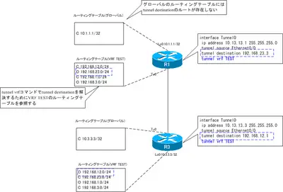
図 tunnel vrfコマンド
Step6:tunnelインタフェースの確認
再度、R1、R3のtunnelインタフェースの状態を確認します。
R1
------------------------------
R1#show interfaces Tunnel 0
Tunnel0 is up, line protocol is up
Hardware is Tunnel
Internet address is 10.13.13.1/24
MTU 1514 bytes, BW 9 Kbit/sec, DLY 500000 usec,
reliability 255/255, txload 1/255, rxload 1/255
Encapsulation TUNNEL, loopback not set
Keepalive not set
Tunnel source 192.168.12.1 (Ethernet0/0), destination 192.168.23.3
Tunnel protocol/transport GRE/IP
Key disabled, sequencing disabled
Checksumming of packets disabled
Tunnel TTL 255
~省略=
------------------------------
R3
------------------------------
R3#show interfaces Tunnel 0
Tunnel0 is up, line protocol is up
Hardware is Tunnel
Internet address is 10.13.13.3/24
MTU 1514 bytes, BW 9 Kbit/sec, DLY 500000 usec,
reliability 255/255, txload 1/255, rxload 1/255
Encapsulation TUNNEL, loopback not set
Keepalive not set
Tunnel source 192.168.23.3 (Ethernet0/0), destination 192.168.12.1
Tunnel protocol/transport GRE/IP
Key disabled, sequencing disabled
Checksumming of packets disabled
Tunnel TTL 255
~省略~
------------------------------
tunnel vrfコマンドによってtunnel destinationのIPアドレスを解決できるようになったので、tunnel0インタフェースがup/upの状態です。
Step7:IKEフェーズ1の設定
R1-R3間でIKEフェーズ1の設定を行います。IKEポリシーとして、以下のとおりとします。
- 暗号化アルゴリズム:AES
- DHグループ:2
- ピア認証:PSK 「cisco」
IKEピアは、VRF TEST上に存在するのでcrypto keyringでVRFを指定しなければいけないことに注意してください。
R1
------------------------------
crypto keyring cisco vrf TEST
pre-shared-key address 192.168.23.3 key cisco
!
crypto isakmp policy 1
encr aes
authentication pre-share
group 2
------------------------------
R3
------------------------------
crypto keyring cisco vrf TEST
pre-shared-key address 192.168.12.1 key cisco
!
crypto isakmp policy 1
encr aes
authentication pre-share
group 2
------------------------------
Step8:IPSecプロファイルの設定
IPSecトランスフォームセットを作成して、IPSecプロファイルに関連付けます。そして、IPSecプロファイルをTunnel0インタフェースに適用します。
R1
------------------------------
crypto ipsec transform-set TS esp-aes esp-sha-hmac
mode transport
!
crypto ipsec profile IPSEC
set transform-set TS
!
interface Tunnel0
tunnel protection ipsec profile IPSEC
------------------------------
R3
------------------------------
crypto ipsec transform-set TS esp-aes esp-sha-hmac
mode transport
!
crypto ipsec profile IPSEC
set transform-set TS
!
interface Tunnel0
tunnel protection ipsec profile IPSEC
------------------------------
Step9:EIGRPの設定
R1、R3ではグローバルのルーティングインスタンス上でTunnel0インタフェースを通じて、EIGRPでルーティングできるようにします。EIGRP AS1を設定します。
R1/R3
------------------------------
router eigrp 1
network 10.0.0.0
no auto-summary
------------------------------
Step10:EIGRPの確認
R1、R3のグローバルルーティングインスタンスでのEIGRPの設定を確認します。
R1
------------------------------
R1#show ip eigrp neighbors
IP-EIGRP neighbors for process 1
H   Address                 Interface       Hold Uptime   SRTT   RTO  Q  Seq
(sec)         (ms)       Cnt Num
0   10.13.13.3              Tu0               12 00:01:37   79  5000  0  3
R1#show ip route eigrp
10.0.0.0/8 is variably subnetted, 3 subnets, 2 masks
D       10.3.3.3/32 [90/297372416] via 10.13.13.3, 00:01:39, Tunnel0
------------------------------
Step11:IPSecの確認
R1-R3間でISAKMP SAとIPSec SAが正常に確立できていることも確認します。
R1
------------------------------
R1#show crypto isakmp sa
dst             src             state          conn-id slot status
192.168.23.3    192.168.12.1    QM_IDLE              1    0 ACTIVE
R1#show crypto ipsec sa
interface: Tunnel0
Crypto map tag: Tunnel0-head-0, local addr 192.168.12.1
protected vrf: TEST
local  ident (addr/mask/prot/port): (192.168.12.1/255.255.255.255/47/0)
remote ident (addr/mask/prot/port): (192.168.23.3/255.255.255.255/47/0)
current_peer 192.168.23.3 port 500
PERMIT, flags={origin_is_acl,}
#pkts encaps: 233, #pkts encrypt: 233, #pkts digest: 233
#pkts decaps: 231, #pkts decrypt: 231, #pkts verify: 231
#pkts compressed: 0, #pkts decompressed: 0
#pkts not compressed: 0, #pkts compr. failed: 0
#pkts not decompressed: 0, #pkts decompress failed: 0
#send errors 42, #recv errors 0
local crypto endpt.: 192.168.12.1, remote crypto endpt.: 192.168.23.3
path mtu 1500, ip mtu 1500, ip mtu idb Ethernet0/0
current outbound spi: 0xEAA52C41(3936693313)
inbound esp sas:
spi: 0x1416F1A1(337047969)
transform: esp-aes esp-sha-hmac ,
in use settings ={Transport, }
conn id: 2001, flow_id: SW:1, crypto map: Tunnel0-head-0
sa timing: remaining key lifetime (k/sec): (4552430/2547)
IV size: 16 bytes
replay detection support: Y
Status: ACTIVE
inbound ah sas:
inbound pcp sas:
outbound esp sas:
spi: 0xEAA52C41(3936693313)
transform: esp-aes esp-sha-hmac ,
in use settings ={Transport, }
conn id: 2002, flow_id: SW:2, crypto map: Tunnel0-head-0
sa timing: remaining key lifetime (k/sec): (4552430/2545)
IV size: 16 bytes
replay detection support: Y
Status: ACTIVE
outbound ah sas:
outbound pcp sas:
------------------------------
Step12:通信確認
VRF TESTとグローバルのルーティングインスタンスでの最終的な通信ができることを確認します。
R1
------------------------------
R1#ping 10.3.3.3 source 10.1.1.1
Type escape sequence to abort.
Sending 5, 100-byte ICMP Echos to 10.3.3.3, timeout is 2 seconds:
Packet sent with a source address of 10.1.1.1
!!!!!
Success rate is 100 percent (5/5), round-trip min/avg/max = 20/36/44 ms
R1#ping vrf TEST 192.168.3.3 source 192.168.1.1
Type escape sequence to abort.
Sending 5, 100-byte ICMP Echos to 192.168.3.3, timeout is 2 seconds:
Packet sent with a source address of 192.168.1.1
!!!!!
Success rate is 100 percent (5/5), round-trip min/avg/max = 28/38/44 ms
------------------------------
有料メールマガジン「ネットワークのおべんきょしませんか? PREMIUM」では、高解像度のMP4ファイルとこのページの内容をまとめたPDFファイル、GNS3プロジェクトファイルをダウンロードできます。