Table of Contents
LAN Design pattern
The network of a company’s site is mainly consisted of Layer 2 switches and Layer 3 switches. A network is divided by VLANs on Layer 2 switches, and the VLANs are interconnected by Layer 3 switches. By using Layer 3 switches, high-speed communication between VLANs can be achieved.
There are two major approaches to designing a LAN for a site using a combination of Layer 2 and Layer 3 switches.
- 2-tier
- 3-tier
2-Tier LAN Design
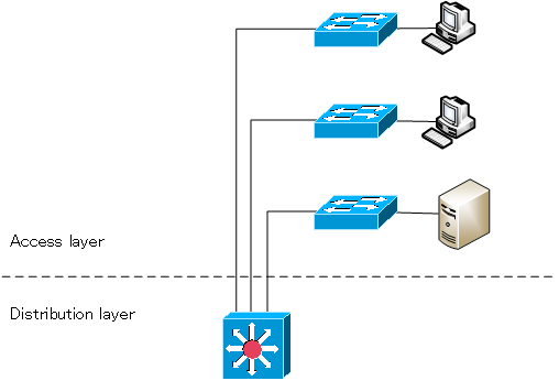
The 2-tier LAN design is a site that looks like it is housed on a floor of a single building. It consists of the following two tiers
- Access layer
- Distribution layer
The access layer is the layer that allows users’ PCs and other devices to access the site’s LAN. In most cases, a layer 2 switch is used. The layer 2 switch of the access layer is called an access switch, and by connecting a PC to the access switch, the user can access the LAN at the site.
The distribution layer is a layer that aggregates access switches to forward data. Mostly, Layer 3 switches are used, and they are called distribution switches. The access switches on each floor are connected to the distribution switches. The VLANs defined by the access switches are interconnected by the distribution switch. The distribution switch enables fast inter-VLAN routing.

3-Tier LAN Design
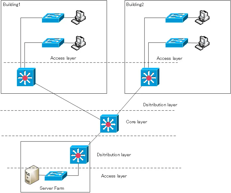
The 3-tier LAN design is a large site with multiple buildings on the site. In addition to the access and distribution layers, we consider core layer. The core layer is also called the backbone layer.
The concept of the access and distribution layers is the same as the 2-tier model. The access layer and distribution layer make up the network of a single building. If you have multiple buildings, you will naturally need to communicate between them as well. The core layer interconnect building’s network. Servers may also be located in server farms, as they are easier to manage if they are centralized. The core layer also provides interconnection to the server farm.
The switches in the core layer are called core switches or backbone switches. You can use a Layer 2 switch as a backbone switch, but it is easier to control the routing if you use a Layer 3 switch.

VLAN(Virtual LAN)
- The need to divide the network
- Details of dividing the network
- VLAN Overview
- VLAN behavior
- Access port : Port assigned to only one VLAN
- Trunk port : Port assigned to multiple VLANs
- Summary of Trunk Protocols – IEEE802.1Q and ISL
- Native VLAN
- Specific example of native VLAN mismatch
- Cisco DTP
- Cisco Configuring and Verifying VLAN
- Cisco VLAN Detailed Configuration Example
- Notes on deleting VLANs
- Voice VLAN – VLAN for connecting IP phones
- VTP :Synchronize VLAN configuration
- VTP pruning – Stopping unnecessary flooding of trunk links
- Configuring and Verifying Cisco VTP
- Inter VLAN routing overview
- Inter-VLAN routing by router
- Inter-VLAN routing by Layer 3 switch
- Configuring and Verifying Inter-VLAN Routing by Cisco Router
- Cisco Configuring Inter-VLAN routing by Layer3 switch : SVI/routed port
- Cisco Layer3 Switch Basic Configuration Example
- Summary of Layer 3 Switch Port Concepts – Access Port/Trunk Port/SVI/Routed Port
- LAN Design pattern : 2-tier and 3-tier
