
Table of Contents
VLAN Behavior Overview
The VLAN is simple in itself. A normal Layer 2 switch allows Ethernet frames to be forwarded between all ports. However, a VLAN restricts it to forward Ethernet frames only between ports that are assigned to the same VLAN. By allowing Ethernet frames to be forwarded only between ports of the same VLAN, the broadcast domain, or network, is divided.
The point of VLAN behavior
The VLAN is very simple! It divides the network by “forwarding Ethernet frames only between ports that are assigned to the same VLAN.
Identify VLANs
VLANs are identified by VLAN numbers, which range from 1 to 4094, and TCP/IP networks are identified by network addresses. When dividing a network by VLANs, it is necessary to consider the correspondence between VLAN numbers and network addresses. To make the correspondence between VLAN numbers and network addresses easier to understand, in most cases, the VLAN number is embedded as part of the network address. For example, VLAN 10 would be mapped to the network address 192.168.10.0/24. This is an example of embedding the VLAN number in the third octet of the network address to make the mapping between VLAN and network address easier to understand.
However, since the range of numbers used in IP addresses is 0-255, some VLAN numbers cannot necessarily be embedded in network addresses. Even in such a case, it is very important to make the correspondence between VLAN numbers and network addresses easy to understand. If there is no consistent policy for mapping VLAN numbers to network addresses, the network configuration will be confusing, and this can lead to problems.
Forwarding Ethernet frames when configuring VLANs
We will consider the forwarding of Ethernet frames when a VLAN is configured on a Layer 2 switch. First, we will consider only one switch to simplify the story.
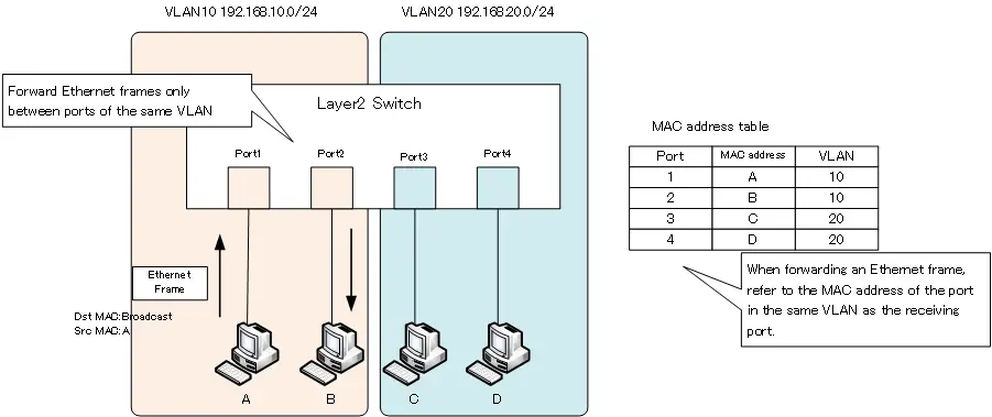
The following figure shows an example of a network diagram using VLANs on a single Layer 2 switch. VLAN10 and VLAN20 are created on the Layer 2 switch, and ports 1 and 2 are assigned to VLAN10. Ports 3 and 4 are assigned to VLAN 20.
When VLANs are configured in this way, the MAC address table will contain not only the port and MAC address, but also the VLAN information. When a broadcast frame is sent from PC A, it is received on port 1 of the Layer 2 switch. To determine the destination of the Ethernet frame, the MAC address of VLAN 10, which is the same as the receiving port, is referenced. In the case of a broadcast MAC address, it is not registered in the MAC address table. In that case, it will be flooded, but the forwarded port will be the only port in the same VLAN 10. In other words, the Layer 2 switch will flood the broadcast frame received on port 1 to port 2 only.
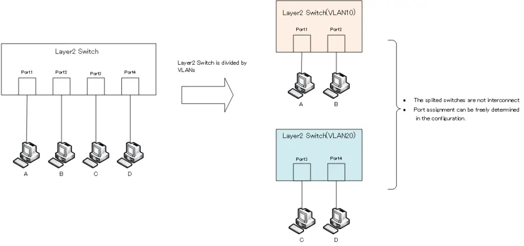
A simple way to think about VLANs is to virtually divide a Layer 2 switch. In the previous example, we are considering two VLANs, VLAN10 and VLAN20. Then, one Layer 2 switch can be treated as two virtual switches. The port of the switch for each divided VLAN can be freely decided depending on the configuration. Also, since the switches for each VLAN are not connected to each other, the network is divided to isolate the forwarding of Ethernet frames between VLANs. The increased security provided by VLANs means that the scope of data (Ethernet frames) forwarding is limited.
VLAN(Virtual LAN)
- The need to divide the network
- Details of dividing the network
- VLAN Overview
- VLAN behavior
- Access port : Port assigned to only one VLAN
- Trunk port : Port assigned to multiple VLANs
- Summary of Trunk Protocols – IEEE802.1Q and ISL
- Native VLAN
- Specific example of native VLAN mismatch
- Cisco DTP
- Cisco Configuring and Verifying VLAN
- Cisco VLAN Detailed Configuration Example
- Notes on deleting VLANs
- Voice VLAN – VLAN for connecting IP phones
- VTP :Synchronize VLAN configuration
- VTP pruning – Stopping unnecessary flooding of trunk links
- Configuring and Verifying Cisco VTP
- Inter VLAN routing overview
- Inter-VLAN routing by router
- Inter-VLAN routing by Layer 3 switch
- Configuring and Verifying Inter-VLAN Routing by Cisco Router
- Cisco Configuring Inter-VLAN routing by Layer3 switch : SVI/routed port
- Cisco Layer3 Switch Basic Configuration Example
- Summary of Layer 3 Switch Port Concepts – Access Port/Trunk Port/SVI/Routed Port
- LAN Design pattern : 2-tier and 3-tier