Table of Contents
EIGRP Metric
EIGRP uses a composite metric. A composite metric is a value calculated from the following five elements
- Bandwidth(BW)
- Delay(DLY)
- Reliability(RELIABILITY)
- Load(LOAD)
- MTU
The specific values of the five elements are predetermined for each interface and can be verified by the show interface command. You can also change them in the configuration.
R1#show interfaces fastEthernet 0/0
FastEthernet0/0 is up, line protocol is up
  Hardware is AmdFE, address is cc01.3180.0000 (bia cc01.3180.0000)
  Internet address is 192.168.12.1/24
  MTU 1500 bytes, BW 100000 Kbit/sec, DLY 100 usec,
     reliability 255/255, txload 1/255, rxload 1/255
  Encapsulation ARPA, loopback not set
  Keepalive set (10 sec)
  Full-duplex, 100Mb/s, 100BaseTX/FX
-- omitted --
The Metric Formula.
Based on the five elements, the metric value is calculated according to the following formula.
K5=0
EIGRP Metric=[K1*BW+K2*BW/(256-LOAD)+K3*DLY] * 256
K5≠0
EIGRP Metric=[K1*BW+K2*BW/(256-LOAD)+K3*DLY]*[K5/(REALIABILITY+K4)] * 256
In this formula, there are coefficients ranging from K1 to K5. These are coefficients that determine the extent to which the five factors, called K-values, are taken into account. The defaults for the K-value are as follows
K1=K3=1、K2=K4=K5=0
This means that by default, the EIGRP metric will be calculated using bandwidth and delay as follows.
Metric=(BW + DLY) * 256
The bandwidth in the calculation of the EIGRP metric uses the minimum value on the route. If there is an interface with low bandwidth on the path to the destination network, it will be dragged down by that part of the network and the value of the metric will be large. The delay is then used as a cumulative value to the destination network. Both bandwidth and delay are applied to the value of the interface on which the EIGRP route information is received.
Note that the BW and DLY values are calculated by scaling them as follows.
BW = 107/minimum bandwidth
DLY = Cumulative delays along the route/10
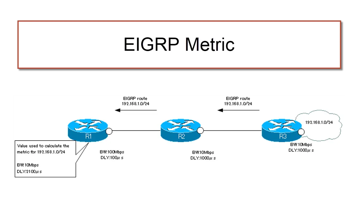
Example of a metric calculation
For example, in the following figure, when calculating the metric for a network of 192.168.1.0/24 in R1, the bandwidth is 10 Mbps (=104 kbps). We use the minimum value on the route. And the delay is 100+1000+1000 = 2100 µs, cumulating the values of the delay on the path.
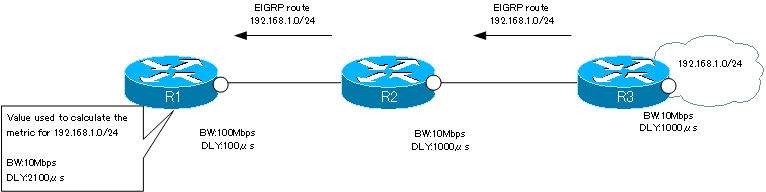
In the example in the figure, the EIGRP metric for 192.168.1.0/24 on R1 can be calculated as follows.
EIGRP Metric = [107 / 104 + 2100/10 ] * 256 = 309760
The details of each element used in these EIGRP metric calculations can be found in the topology table.
R1#show ip eigrp topology 192.168.1.0
IP-EIGRP (AS 1): Topology entry for 192.168.1.0/24
  State is Passive, Query origin flag is 1, 1 Successor(s), FD is 309760
  Routing Descriptor Blocks:
  192.168.12.2 (FastEthernet0/0), from 192.168.12.2, Send flag is 0x0
      Composite metric is (309760/307200), Route is Internal
      Vector metric:
        Minimum bandwidth is 10000 Kbit
        Total delay is 2100 microseconds
        Reliability is 255/255
        Load is 1/255
        Minimum MTU is 1500
        Hop count is 2
Neighbor Condition
EIGRP cannot establish neighbors between routers with different K-values, because different K-values mean different metric formulas, which make the determination of the optimal route inconsistent. The conditions for establishing a neighbor in EIGRP can be summarized again as follows.
- Same AS number
- Same K-values
In addition to the above, the neighbors must be on the same network, and care must be taken in configuring IP addresses and subnet masks. Note that the K-value is rarely changed and the default value is usually used.