Table of Contents
GRE Tunnel interface Overview
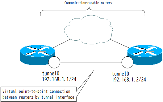
The GRE (Generic Routing Encapsulation) tunnel interface is a virtual point-to-point connection between two routers that can communicate. It is also known simply as a tunnel interface.

The GRE tunnel interface is used for Internet VPN and other applications. It can also be used for IPv6 communication over an IPv4 network.
Configuring the GRE Tunnel Interface
The steps for configuring the GRE tunnel interface are as follows
- Creating a Tunnel Interface
- Configuring tunnel destination/tunnel source
- Configuring IP address
Creating a Tunnel Interface
To create the tunnel interface, use the following command in global configuration mode.
(config)#interface Tunnel <num>
(config-if)#
<num> : interface number
Configuring tunnel destination/tunnel source
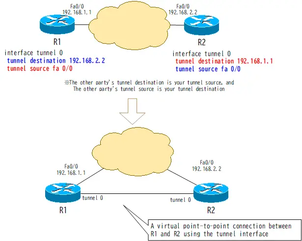
Next, specify the IP address of the forwarding IPv4 header. tunnell destination command specifies the destination IP address of the forwarding IPv4 header and tunnell source command specifies the source IP address of the forwarding IPv4 header.
(config)#interface Tunnel <num>
(config-if)#tunnel destination <dst-ip-address>
(config-if)#tunnel source <source-ip-address|source-interface>
<num> : interface number
<dst-ip-address> : Destination IP address of the encapsulating IP header
<source-ip-address> : Source IP address of the encapsulating IP header
<source-interface> : Interface to be used as the source IP address of the encapsulating IP header
If the IP address specified by the tunnel destination can be reached, the tunnel interface will be in the up/up state. However, both routers on which you configure tunnels must have the other party’s tunnel destination set to their own tunnel source and the other party’s tunnel source set to their own tunnel destination. If the tunnel destination and tunnel source configurations are correct, both routers with tunnels configured will look as if they are directly connected point-to-point.

Configuring IP address
An IP address is required for IP communication on the tunnel interface. The tunnel interface is configured with an IP address just like a normal interface. As I have repeatedly stated, remember that you can only connect to the network and communicate with it when you configure the IP address.
(config)#interface Tunnel <num>
(config-if)#ip address <address> <subnetmask>
<num> : interface number
<address> : IP address
<subnetmask> : subnet mask
The IP address of the tunnel interface is often configured to use the IP address of another interface by ip unnumbered command.
Forwarding IP packets from the GRE tunnel interface
IP packets sent from the tunnel interface are encapsulated in GRE headers and IPv4 headers for forwarding. The destination/source IP address of the forwarding IPv4 header is the IP address configured in the tunnel destination/tunnel source. It is then output from the associated physical interface. The associated physical interface is determined from the routing table and tunnel destination. In addition, when the output from the physical interface is sent out, it is encapsulated in a Layer 2 protocol, such as Ethernet, that is appropriate for the physical interface. Finally, the output is sent out as a physical signal, such as an electrical signal, to the transmission medium.

When the GRE tunnel goes down
If there is no connectivity to the tunnel destination of the tunnel interface, the tunnel interface will be in an up/down state, as shown in the following command output.
R1#show ip interface brief
Interface                  IP-Address      OK? Method Status                Protocol
FastEthernet0/0            192.168.1.1     YES NVRAM  up                    up
FastEthernet0/1            192.168.0.1     YES NVRAM  up                    up
Loopback0                  10.1.1.1        YES NVRAM  up                    up
Tunnel13                   172.16.1.1      YES manual up                    down
Make sure that connectivity to the tunnel destination is properly established. By default, connectivity to the tunnel destination is verified based on the routing table.
Advanced IP Routing
- Overview of Cisco Route-map
- Cisco Route-map Configuration
- GRE Tunnel Interface – Virtual Point-to-Point Connection
- GRE Tunnel Interface Configuration Example
- Overview of VRF/VRF-Lite – Virtually separating the router –
- Cisco VRF Configuration and Verification Commands
- Cisco Layer 3 VPN with VRF-Lite Configuration Example
- What Is FVRF(Front door VRF)?
- Point-to-point GRE Tunnel without FVRF
- Point-to-point GRE tunnel with FVRF (tunnel vrf command)
- IPSec VTI with FVRF
- IPSec VTI with FVRF Configuration Example
- DMVPN with FVRF
- DMVPN with FVRF Configuration Example Part1
- DMVPN with FVRF Configuration Example Part2