
Table of Contents
Overview
Layer 3 VPN is built by virtually separating the router by VRF-Lite. The configuration itself is very simple. Note that when using VRF, the VRF must be specified in the verification commands such as show ip route and Ping.
Related article
Please also refer to the following article about the configuration commands for VRF-Lite.
Network Diagram
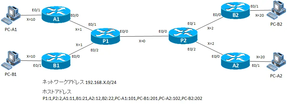
Configuration Requirement
- Build a Layer 3 VPN to allow communication between Company A’s PC-A1 and PC-A2. In addition, a Layer 3 VPN will be built to allow communication between Company B’s PC-B1 and PC-B2.
- The VRF name and RD to be configured in P1/P2 are as follows.
| Router | VRF name | RD | Interface |
|---|---|---|---|
| P1 | VRF-A | 10:10 | E0/1 E0/0.10 Lo1 |
| VRF-B | 20:20 | E0/2 E0/0.20 Lo2 | |
| P2 | VRF-A | 10:10 | E0/2 E0/0.10 Lo1 |
| VRF-B | 20:20 | E0/1 E0/0.20 Lo2 |
- The IP addresses of Lo1 and Lo2 for P1 and P2 are set to the same addresses as Lo0.
- Configure the routing as shown in the table below.
| VRF | Router | Routing Protocol |
|---|---|---|
| グローバル | P1-P2 | EIGRP AS100 |
| VRF-A | A1-P1,P1-P2,A2-P2 | OSPFエリア0 |
| VRF-B | B1-P1,P1-P2,P2-B2 | EIGRP AS20 |
Initial Configuration
Start with host names and IP addresses as the initial configuration. The P1/P2 configuration is for the global routing process IP address only. An excerpt of the initial configuration for each device is as follows
P1 Configuration Excerpts (Click)
hostname P1
!
interface Loopback0
 ip address 192.168.100.1 255.255.255.255
!
interface Ethernet0/0
 ip address 192.168.0.1 255.255.255.0
P2 Configuration Excerpts (Click)
hostname P2
!
interface Loopback0
 ip address 192.168.100.2 255.255.255.255
!
interface Ethernet0/0
 ip address 192.168.0.2 255.255.255.0
A1 Configuration Excerpts (Click)
hostname A1
!
interface Loopback0
 ip address 192.168.100.11 255.255.255.255
!
interface Ethernet0/0
 ip address 192.168.1.11 255.255.255.0
!
interface Ethernet0/1
 ip address 192.168.10.11 255.255.255.0
A2 Configuration Excerpts (Click)
hostname A2
!
interface Loopback0
 ip address 192.168.100.12 255.255.255.0
!
interface Ethernet0/0
 ip address 192.168.2.12 255.255.255.0
!
interface Ethernet0/1
 ip address 192.168.20.12 255.255.255.0
B1 Configuration Excerpts (Click)
hostname B1
!
interface Loopback0
 ip address 192.168.100.21 255.255.255.255
!
interface Ethernet0/0
 ip address 192.168.1.21 255.255.255.0
!
interface Ethernet0/1
 ip address 192.168.10.21 255.255.255.0
B2 Configuration Excerpts (Click)
hostname B2
!
interface Loopback0
 ip address 192.168.100.22 255.255.255.255
!
interface Ethernet0/0
 ip address 192.168.2.22 255.255.255.0
!
interface Ethernet0/1
 ip address 192.168.20.22 255.255.255.0
PC-A1 Configuration Excerpts (Click)
hostname PC-A1
!
no ip routing
!
interface Ethernet0/0
 ip address 192.168.10.101 255.255.255.0
!
ip default-gateway 192.168.10.11
PC-A2 Configuration Excerpts (Click)
hostname PC-A2
!
no ip routing
!
interface Ethernet0/0
 ip address 192.168.20.102 255.255.255.0
!
ip default-gateway 192.168.20.12
PC-B1 Configuration Excerpts (Click)
hostname PC-B1
!
no ip routing
!
interface Ethernet0/0
 ip address 192.168.10.201 255.255.255.0
!
ip default-gateway 192.168.10.21
PC-B2 Configuration Excerpts (Click)
hostname PC-B2
!
no ip routing
!
interface Ethernet0/0
 ip address 192.168.20.202 255.255.255.0
!
ip default-gateway 192.168.20.22
Configuration and Verification
Step1: VRF Configuration
Based on the Table VRF configuration, create VRFs and assign interfaces in P1 and P2. Between P1 and P2, a sub-interface is created for each VRF to assign VRFs and configure IP addresses.
P1 VRF Configuration
ip vrf VRF-A
 rd 10:10
!
ip vrf VRF-B
 rd 20:20
!
interface Loopback1
 ip vrf forwarding VRF-A
 ip address 192.168.100.1 255.255.255.255
!
interface Loopback2
 ip vrf forwarding VRF-B
 ip address 192.168.100.1 255.255.255.255
!
interface Ethernet0/0.10
 encapsulation dot1Q 10
 ip vrf forwarding VRF-A
 ip address 192.168.0.1 255.255.255.0
!
interface Ethernet0/0.20
 encapsulation dot1Q 20
 ip vrf forwarding VRF-B
 ip address 192.168.0.1 255.255.255.0
!
interface Ethernet0/1
 ip vrf forwarding VRF-A
 ip address 192.168.1.1 255.255.255.0
!
interface Ethernet0/2
 ip vrf forwarding VRF-B
 ip address 192.168.1.1 255.255.255.0
P2 VRF Configuration
ip vrf VRF-A
 rd 10:10
!
ip vrf VRF-B
 rd 20:20
!
interface Loopback1
 ip vrf forwarding VRF-A
 ip address 192.168.100.2 255.255.255.255
!
interface Loopback2
 ip vrf forwarding VRF-B
 ip address 192.168.100.2 255.255.255.255
!
interface Ethernet0/0.10
 encapsulation dot1Q 10
 ip vrf forwarding VRF-A
 ip address 192.168.0.2 255.255.255.0
!
interface Ethernet0/0.20
 encapsulation dot1Q 20
 ip vrf forwarding VRF-B
 ip address 192.168.0.2 255.255.255.0
!
interface Ethernet0/1
 ip vrf forwarding VRF-B
 ip address 192.168.2.2 255.255.255.0
!
interface Ethernet0/2
 ip vrf forwarding VRF-A
 ip address 192.168.2.2 255.255.255.0
Step2: VRF Verification
Verify the VRF status with the show ip vrf command on P1 and P2. Also verify the global routing table and the routing table of the VRF; for P1, the following is displayed.
P1 VRF Verification
P1#show ip vrf
Name Default RD Interfaces
VRF-A 10:10 Et0/1
Lo1
Et0/0.10
VRF-B 20:20 Et0/2
Lo2
Et0/0.20
P1#show ip vrf detail
VRF VRF-A; default RD 10:10; default VPNID
Step3: Configure global routing process
Global routing process routing by EIGRP on P1 and P2.
P1/P2 Configure global routing process
router eigrp 100
 network 192.168.0.0 0.0.255.255
 no auto-summary
Step4: Verify global routing process
Verify the routing of the global routing process on P1 and P2.
- show ip eigrp neighbor
- show ip route
On P1, the output results are as follows.
P1 Verify global routing process
P1#show ip eigrp neighbors
IP-EIGRP neighbors for process 100
H   Address                 Interface       Hold Uptime   SRTT   RTO  Q  Seq
                                            (sec)         (ms)       Cnt Num
0   192.168.0.2             Et0/0             12 00:01:29   17   200  0  3
P1#show ip route
Codes: C - connected, S - static, R - RIP, M - mobile, B - BGP
       D - EIGRP, EX - EIGRP external, O - OSPF, IA - OSPF inter area
       N1 - OSPF NSSA external type 1, N2 - OSPF NSSA external type 2
       E1 - OSPF external type 1, E2 - OSPF external type 2
       i - IS-IS, su - IS-IS summary, L1 - IS-IS level-1, L2 - IS-IS level-2
       ia - IS-IS inter area, * - candidate default, U - per-user static route
       o - ODR, P - periodic downloaded static route

Gateway of last resort is not set

C    192.168.0.0/24 is directly connected, Ethernet0/0
     192.168.100.0/32 is subnetted, 2 subnets
C       192.168.100.1 is directly connected, Loopback0
D       192.168.100.2 [90/409600] via 192.168.0.2, 00:01:30, Ethernet0/0
P1#ping 192.168.100.2 source loopback 0

Type escape sequence to abort.
Sending 5, 100-byte ICMP Echos to 192.168.100.2, timeout is 2 seconds:
Packet sent with a source address of 192.168.100.1
!!!!!
Success rate is 100 percent (5/5), round-trip min/avg/max = 12/19/24 ms
The following is a diagram of the routing of the global routing process.
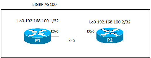
Step5: Configure VRF-A routing
Configure routing for VRF-A. Routing is performed in a single area configuration in OSPF area 0. OSPF specifies VRF when enabling the routing process.
P1/P2 Configure VRF-A routing
router ospf 1 vrf VRF-A
 network 192.168.0.0 0.0.255.255 area 0
A1/A2 Configure routing
router ospf 1
 network 192.168.0.0 0.0.255.255 area 0
Step6: Verify VRF-A routing
Verify VRF-A routing on P1 and P2.
- show ip ospf neighbor
- show ip route vrf VRF-A
- ping vrf VRF-A
On P1, the output is as follows.
P1 Verify VRF-A routing
P1#show ip ospf neighbor

Neighbor ID     Pri   State           Dead Time   Address         Interface
192.168.100.11    1   FULL/DR         00:00:35    192.168.1.11    Ethernet0/1
192.168.100.2     1   FULL/DR         00:00:35    192.168.0.2     Ethernet0/0.10
P1#show ip route vrf VRF-A

Routing Table: VRF-A
Codes: C - connected, S - static, R - RIP, M - mobile, B - BGP
       D - EIGRP, EX - EIGRP external, O - OSPF, IA - OSPF inter area
       N1 - OSPF NSSA external type 1, N2 - OSPF NSSA external type 2
       E1 - OSPF external type 1, E2 - OSPF external type 2
       i - IS-IS, su - IS-IS summary, L1 - IS-IS level-1, L2 - IS-IS level-2
       ia - IS-IS inter area, * - candidate default, U - per-user static route
       o - ODR, P - periodic downloaded static route

Gateway of last resort is not set

O    192.168.10.0/24 [110/20] via 192.168.1.11, 00:04:40, Ethernet0/1
O    192.168.20.0/24 [110/30] via 192.168.0.2, 00:04:40, Ethernet0/0.10
C    192.168.0.0/24 is directly connected, Ethernet0/0.10
C    192.168.1.0/24 is directly connected, Ethernet0/1
O    192.168.2.0/24 [110/20] via 192.168.0.2, 00:04:40, Ethernet0/0.10
     192.168.100.0/32 is subnetted, 4 subnets
O       192.168.100.12 [110/21] via 192.168.0.2, 00:04:40, Ethernet0/0.10
O       192.168.100.11 [110/11] via 192.168.1.11, 00:04:41, Ethernet0/1
C       192.168.100.1 is directly connected, Loopback1
O       192.168.100.2 [110/11] via 192.168.0.2, 00:04:41, Ethernet0/0.10
P1#ping vrf VRF-A 192.168.10.101 source loopback 1

Type escape sequence to abort.
Sending 5, 100-byte ICMP Echos to 192.168.10.101, timeout is 2 seconds:
Packet sent with a source address of 192.168.100.1
!!!!!
Success rate is 100 percent (5/5), round-trip min/avg/max = 20/29/40 ms
P1#ping vrf VRF-A 192.168.20.102 source loopback 1

Type escape sequence to abort.
Sending 5, 100-byte ICMP Echos to 192.168.20.102, timeout is 2 seconds:
Packet sent with a source address of 192.168.100.1
!!!!!
Success rate is 100 percent (5/5), round-trip min/avg/max = 40/48/64 ms
The VRF-A routing is configured as follows.
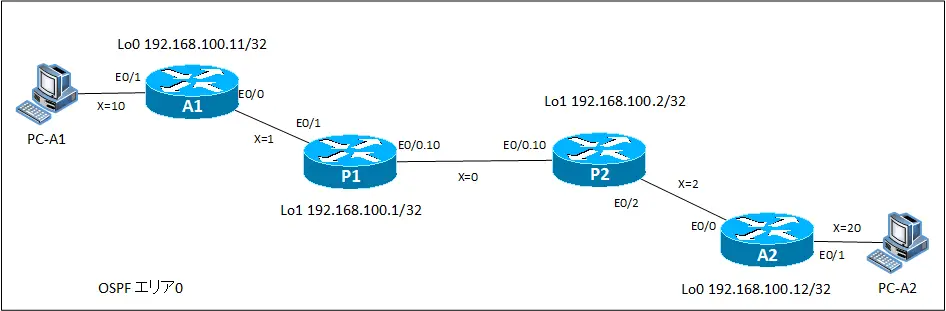
This completes the configuration and verification of the VPN using VRF for Company A, which allows communication only with Company A.
Step7: Configure VRF-B routing
Configure the VRF-B routing. In EIGRP, specify VRF as address-family.
P1/P2 Configure VRF-B Routing
router eigrp 100
 address-family ipv4 vrf VRF-B
  autonomous-system 20
  network 192.168.0.0 0.0.255.255
  no auto-summary
The AS number specification for EIGRP for VRF can also be configured as follows
router eigrp 100
address-family ipv4 vrf VRF-B autonomous-system 20
B1/B2 Configure routing
router eigrp 20
 network 192.168.0.0 0.0.255.255
 no auto-summary
Step8: Verify VRF-B routing
Verify VRF-B routing on P1 and P2.
- show ip eigrp vrf VRF-B neighbor
- show ip route vrf VRF-B
- ping vrf VRF-B
On P1, the output is as follows.
P1 Verify VRF-B routing
P1#show ip eigrp vrf VRF-B neighbors
IP-EIGRP neighbors for process 20
H   Address                 Interface       Hold Uptime   SRTT   RTO  Q  Seq
                                            (sec)         (ms)       Cnt Num
1   192.168.1.21            Et0/2             10 00:00:23   16   200  0  3
0   192.168.0.2             Et0/0.20          13 00:01:33   21   200  0  12
P1#show ip route vrf VRF-B

Routing Table: VRF-B
Codes: C - connected, S - static, R - RIP, M - mobile, B - BGP
       D - EIGRP, EX - EIGRP external, O - OSPF, IA - OSPF inter area
       N1 - OSPF NSSA external type 1, N2 - OSPF NSSA external type 2
       E1 - OSPF external type 1, E2 - OSPF external type 2
       i - IS-IS, su - IS-IS summary, L1 - IS-IS level-1, L2 - IS-IS level-2
       ia - IS-IS inter area, * - candidate default, U - per-user static route
       o - ODR, P - periodic downloaded static route

Gateway of last resort is not set

D    192.168.10.0/24 [90/307200] via 192.168.1.21, 00:00:35, Ethernet0/2
D    192.168.20.0/24 [90/332800] via 192.168.0.2, 00:00:22, Ethernet0/0.20
C    192.168.0.0/24 is directly connected, Ethernet0/0.20
C    192.168.1.0/24 is directly connected, Ethernet0/2
D    192.168.2.0/24 [90/307200] via 192.168.0.2, 00:00:26, Ethernet0/0.20
     192.168.100.0/32 is subnetted, 4 subnets
C       192.168.100.1 is directly connected, Loopback2
D       192.168.100.2 [90/409600] via 192.168.0.2, 00:01:46, Ethernet0/0.20
D       192.168.100.21 [90/409600] via 192.168.1.21, 00:00:36, Ethernet0/2
D       192.168.100.22 [90/435200] via 192.168.0.2, 00:00:24, Ethernet0/0.20
P1#ping vrf VRF-B 192.168.10.201 source loopback 2

Type escape sequence to abort.
Sending 5, 100-byte ICMP Echos to 192.168.10.201, timeout is 2 seconds:
Packet sent with a source address of 192.168.100.1
!!!!!
Success rate is 100 percent (5/5), round-trip min/avg/max = 20/37/48 ms
P1#ping vrf VRF-B 192.168.20.202 source loopback 2

Type escape sequence to abort.
Sending 5, 100-byte ICMP Echos to 192.168.20.202, timeout is 2 seconds:
Packet sent with a source address of 192.168.100.1
!!!!!
Success rate is 100 percent (5/5), round-trip min/avg/max = 24/39/44 ms
The routing configuration for VRF-B is as follows.
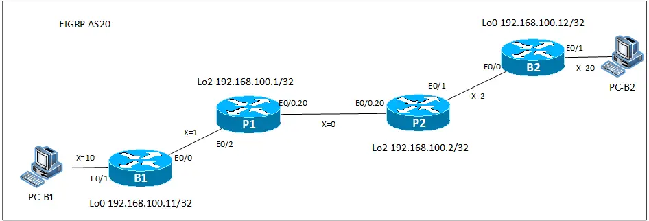
This completes the configuration and verification of the VPN for Company B. Company A and Company B have overlapping address ranges. But since P1/P2 are separated by VRF, there is no problem even if the address ranges of Company A and Company B overlap.
Advanced IP Routing
- Overview of Cisco Route-map
- Cisco Route-map Configuration
- GRE Tunnel Interface – Virtual Point-to-Point Connection
- GRE Tunnel Interface Configuration Example
- Overview of VRF/VRF-Lite – Virtually separating the router –
- Cisco VRF Configuration and Verification Commands
- Cisco Layer 3 VPN with VRF-Lite Configuration Example
- What Is FVRF(Front door VRF)?
- Point-to-point GRE Tunnel without FVRF
- Point-to-point GRE tunnel with FVRF (tunnel vrf command)
- IPSec VTI with FVRF
- IPSec VTI with FVRF Configuration Example
- DMVPN with FVRF
- DMVPN with FVRF Configuration Example Part1
- DMVPN with FVRF Configuration Example Part2