Table of Contents
Overview
Configure a GRE tunnel via the Internet. This creates a virtual point-to-point connection between the two locations.
Network Diagram
Configure a GRE tunnel between R11 and R21 in the following network diagram. the GRE tunnel provides a virtual point-to-point connection between R11 and R21.
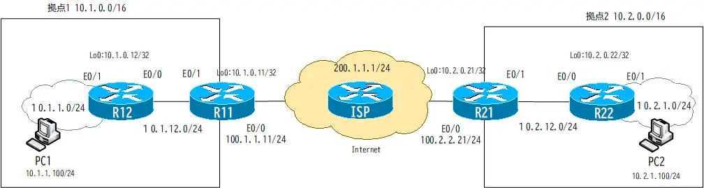
To configure the GRE tunnel interface, it is assumed that communication is available between R11 and R21.
Configuring and Verifying the GRE Tunnel Interface
Configuring GRE Tunnel Interface
Create a tunnel interface with R11 and R21. You can use any interface number, in this case 0. You can use the tunnel destination and tunnel source commands to specify the destination and source IP addresses of the IP headers for forwarding. You also need the IP address to send and receive IP packets on Tunnel0. Instead of configuring the IP address explicitly, we configure ip unnumbered to use the IP address of Loopback0.
R11
interface Tunnel0
 ip unnumbered Loopback0
 tunnel source Ethernet0/0
 tunnel destination 100.2.2.21
R21
interface Tunnel0
 ip unnumbered Loopback0
 tunnel source Ethernet0/0
 tunnel destination 100.1.1.11
Verifying GRE Tunnel Interface
The show interface tunnel0 command verifies the tunnel interface between R11 and R21. the output of show interface tunnel0 at R11 is as follows.
R11
R11#show interfaces tunnel 0
Tunnel0 is up, line protocol is up
  Hardware is Tunnel
  Interface is unnumbered. Using address of Loopback0 (10.1.0.11)
  MTU 1514 bytes, BW 9 Kbit/sec, DLY 500000 usec,
     reliability 255/255, txload 1/255, rxload 1/255
  Encapsulation TUNNEL, loopback not set
  Keepalive not set
  Tunnel source 100.1.1.11 (Ethernet0/0), destination 100.2.2.21
  Tunnel protocol/transport GRE/IP
    Key disabled, sequencing disabled
    Checksumming of packets disabled
  Tunnel TTL 255
  Fast tunneling enabled
  Tunnel transmit bandwidth 8000 (kbps)
  Tunnel receive bandwidth 8000 (kbps)
-- omitted --
Enable RIP on tunnel interface
Configure routing with RIP so that communication between Site1 and Site2 is possible via the GRE tunnel.
R11/R12/R21/R22
router rip
 network 10.0.0.0
 version 2
 no auto-summary
The GRE tunnel is ip unnumbered and has the same IP address as Loopback0. Therefore, if RIP is enabled on Loopback0, RIP will be enabled on tunnel0 at the same time.
Verify Routing
RIP is enabled in the GRE tunnel, and we are able to learn the route information of each other’s sites via the GRE tunnel. the routing status in R11 is as follows
R11
R11#show ip protocols
Routing Protocol is "rip"
  Outgoing update filter list for all interfaces is not set
  Incoming update filter list for all interfaces is not set
  Sending updates every 30 seconds, next due in 20 seconds
  Invalid after 180 seconds, hold down 180, flushed after 240
  Redistributing: rip
  Default version control: send version 2, receive version 2
    Interface             Send  Recv  Triggered RIP  Key-chain
    Ethernet0/1           2     2
    Loopback0             2     2
    Tunnel0               2     2
  Automatic network summarization is not in effect
  Maximum path: 4
  Routing for Networks:
    10.0.0.0
  Routing Information Sources:
    Gateway         Distance      Last Update
    10.1.12.12           120      00:00:01
    10.2.0.21            120      00:00:27
  Distance: (default is 120)

R11#show ip route
~省略~

Gateway of last resort is 100.1.1.100 to network 0.0.0.0

     100.0.0.0/24 is subnetted, 1 subnets
C       100.1.1.0 is directly connected, Ethernet0/0
     10.0.0.0/8 is variably subnetted, 8 subnets, 2 masks
R       10.2.12.0/24 [120/1] via 10.2.0.21, 00:00:03, Tunnel0
C       10.1.12.0/24 is directly connected, Ethernet0/1
R       10.1.0.12/32 [120/1] via 10.1.12.12, 00:00:05, Ethernet0/1
R       10.2.1.0/24 [120/2] via 10.2.0.21, 00:00:03, Tunnel0
R       10.1.1.0/24 [120/1] via 10.1.12.12, 00:00:05, Ethernet0/1
C       10.1.0.0/24 is directly connected, Loopback0
R       10.2.0.21/32 [120/1] via 10.2.0.21, 00:00:04, Tunnel0
R       10.2.0.22/32 [120/2] via 10.2.0.21, 00:00:04, Tunnel0
S*   0.0.0.0/0 [1/0] via 100.1.1.100
Verifying communication between sites
Verify the communication between PC1 and PC2. Execute a ping from PC1 to PC2.
PC1
PC1> ping 10.2.1.100
84 bytes from 10.2.1.100 icmp_seq=1 ttl=60 time=103.327 ms
84 bytes from 10.2.1.100 icmp_seq=2 ttl=60 time=89.114 ms
84 bytes from 10.2.1.100 icmp_seq=3 ttl=60 time=78.018 ms
84 bytes from 10.2.1.100 icmp_seq=4 ttl=60 time=98.787 ms
84 bytes from 10.2.1.100 icmp_seq=5 ttl=60 time=102.156 ms
ICMP packets when pinging from PC1 to PC2 will be output from the tunnel0 interface on R11.
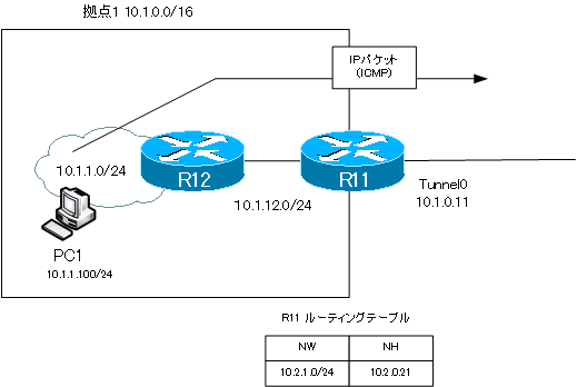
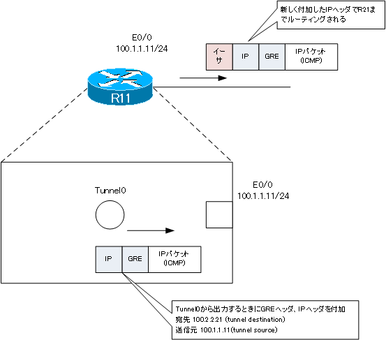
When output from the tunnel0 interface, a GRE header and a new IP header are added and output from E0/0. It will be routed to R21 with the new IP header.
Advanced IP Routing
- Overview of Cisco Route-map
- Cisco Route-map Configuration
- GRE Tunnel Interface – Virtual Point-to-Point Connection
- GRE Tunnel Interface Configuration Example
- Overview of VRF/VRF-Lite – Virtually separating the router –
- Cisco VRF Configuration and Verification Commands
- Cisco Layer 3 VPN with VRF-Lite Configuration Example
- What Is FVRF(Front door VRF)?
- Point-to-point GRE Tunnel without FVRF
- Point-to-point GRE tunnel with FVRF (tunnel vrf command)
- IPSec VTI with FVRF
- IPSec VTI with FVRF Configuration Example
- DMVPN with FVRF
- DMVPN with FVRF Configuration Example Part1
- DMVPN with FVRF Configuration Example Part2