Table of Contents
Overview
Consider the configuration for separating underlay and overlay networks with FVRF in DMVPN (Dynamic Multipoint VPN) Internet VPN .
Related article
See also the following articles about overlay and underlay networks.
See also the following article about FVRF.
DMVPN(Dynamic Multipoint VPN) Overview
The default GRE tunnel or IPSec VTI is a point-to-point connection. If there are multiple sites communicating via Internet VPN, point-to-point connections are not efficient. Tunnel interface configurations can be complicated.
Therefore, we use DMVPN, which is based on multipoint GRE (hereafter referred to as mGRE) tunnels. The mGRE tunnel allows for a multi-access overlay network. That is, an overlay network that allows two or more routers to be connected on the same network. Routing protocols can be run on the mGRE tunnel to dynamically learn route information via the overlay network. However, mGRE tunnels are not broadcast multi-access networks like Ethernet. It is a non-broadcast multi-access network like Frame Relay. Therefore, a little additional configuration is required to make routing protocols such as OSPF/EIGRP work.
The data communicated via the mGRE tunnel is then encrypted with IPSec and transferred over the underlay network. After automatically establishing ISAKMP/IPSec SA between appropriate routers, the data is encrypted, encapsulated with appropriate headers, and forwarded over the Internet (underlay network). When point-to-point GRE tunnels, the destination IP address of the new IP header to be encapsulated is preconfigured. The mGRE tunnel dynamically resolves the destination IP address of the new IP header by NHRP.

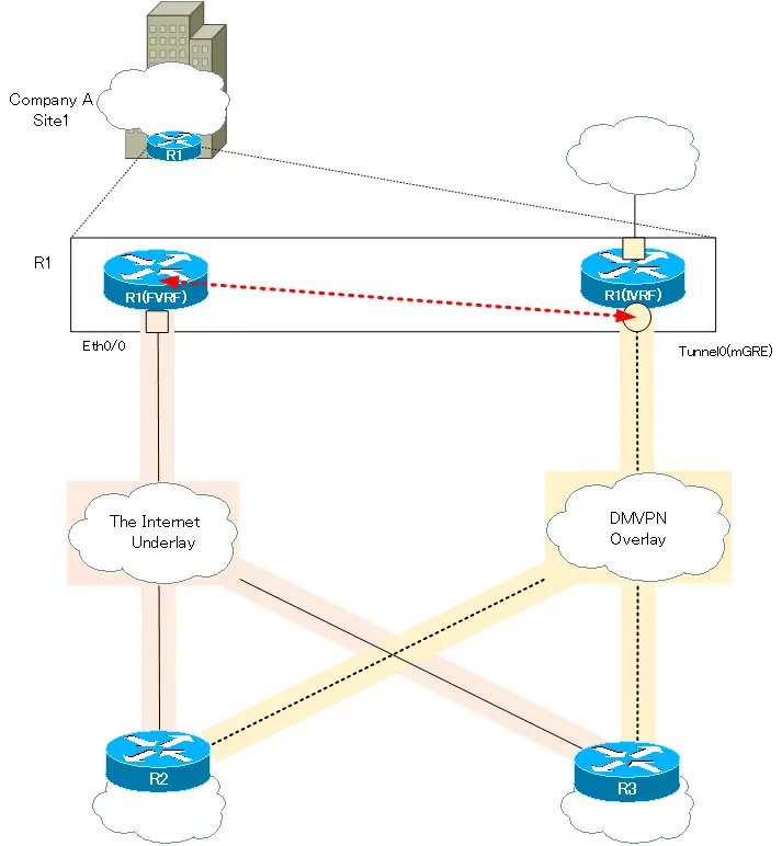
Similar to point-to-point GRE tunnels, the DMVPN mGRE tunnel (overlay network) and the Internet (underlay network) can be logically separated by VRF.
Overlay Network VRF : FVRF
Underlay Network VRF : IVRF
The following figure shows how the overlay and underlay networks are separated by VRF only for the router at Company A site 1.

Key Points for DMVPN (VRF-aware) Configuration
mGRE Tunnel Interface
The important thing about the mGRE tunnel interface is the configuration about NHRP. Allows NHRP to dynamically resolve the correspondence between the IP address of the overlay network and the IP address of the underlay network. NHRP itself has little to do with VRF, but let’s look back at the NHRP commands. Note that what we are describing here is NHRP Phase 2.
NHS NHRP Configuration
The mGRE configuration commands for the Next Hop Server (NHS), which manages the correspondence between overlay and underlay IP addresses, are as follows.
NHS NHRP Configuration
(config)#interface tunnel <interface-number>
(config-if)#tunnel mode gre multipoint
(config-if)#tunnel source {<source-address>|<source-interface>}
(config-if)#ip nhrp network-id <network-id>
(config-if)#ip nhrp map multicast dynamic
<interface-number> : Interface number
<source-address>|<source-interface> : Source IP address | interface of newly added IP header
<network-id> : Network ID
Use the tunnel mode gre multipoint command to make it an mGRE interface. mGRE configuration does not need tunnel destination. The destination IP address of the underlay network is resolved by NHRP.
The tunnel source command determines the source IP address of the new IP header to be added when forwarding over an underlay. tunnel source is the IP address of the underlay.
Specify arbitrary network ID with the ip nhrp network-id command. The network ID is meaningful locally and does not have to match other devices. However, it is usually specified as a network ID that is common to all devices on the mGRE tunnel.
Then, the ip nhrp map multicast dynamic command allows multicast (broadcast) packets to be forwarded in unicast (underlay) to dynamically learned NHCs. Since mGRE is a non-broadcast multi-access network, this configuration is to allow pseudo-broadcasting.
NHC NHRP Configuration
The NHC registers information on its own overlay and underlay addresses with the NHS. And the underlay network address is needed when forwarding packets on mGRE. To do so, NHC will query the NHS for the required underlay address.
The mGRE configuration command for NHC (Next Hop Client) is as follows.
NHC NHRP Configuration
(config)#interface tunnel <interface-number>
(config-if)#tunnel mode gre multipoint
(config-if)#tunnel source {<source-address>|<source-interface>}
(config-if)#ip nhrp network-id <network-id>
(config-if)#ip nhrp map <nhs-overlay-address> <nhs-underlay-address>
(config-if)#ip nhrp nhs <nhs-overlay-address>
(config-if)#ip nhrp map multicast <nhs-underlay-address>
<interface-name> : Interface number
<source-address>|<source-interface> : Source IP address | interface of newly added IP header
<network-id> : Network ID
<nhs-overlay-address> : Overlay address of NHS
<nhs-underlay-address> : Underlay address of NHS
The NHC registers the correspondence between its own overlay and underlay addresses with the NHS. Configure the overlay address of the NHS to which registered by using the ip nhrp nhs command. Then, configure the underlay address corresponding to the overlay address of the NHS with the ip nhrp map command.
Configure the underlay address to encapsulate when forwarding multicast (broadcast) over the mGRE tunnel with the ip nhrp map multicast command. In most cases, the NHS underlay address is specified. This means that multicast (broadcast) is most often configured to forward only to the NHS.
From the Cisco official NHRP command syntax, this page uses slightly different wording for option names.
tunnel address → overlay address
NBMA address → underlay
We believe the terms “overlay” and “underlay” are easier to understand.
Depending on the IOS version, the three commands can be configured together.
(config-if)#ip nhrp map <nhs-overlay-address> <nhs-underlay-address>
(config-if)#ip nhrp nhs <nhs-overlay-address>
(config-if)#ip nhrp map multicast <nhs-underlay-address>
↓
(config)#ip nhrp nhs <nhs-overlay-address> nbma <nhs-underlay-address> multicast
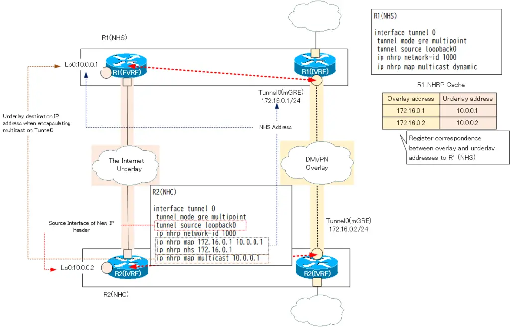
The following diagram is a simple example of the NHS/NHS commands so far. For simplicity, only one NHC is used; think similarly when adding additional NHCs.

In this example, the IP address of Lo0 in FVRF is used as the underlay address. The underlay address does not necessarily have to be the IP address of the physical interface. Connectivity through the underlay network is acceptable.
NHS/NHC VRF and IPSec Configuration
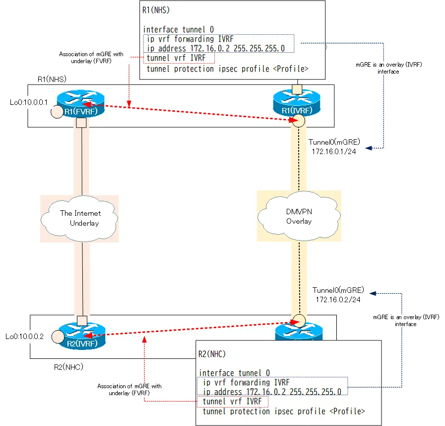
In common with NHS/NHC, the mGRE tunnel is configured as follows. These configurations are for separating the mGRE tunnel and underlay with VRF and encrypting the data in the mGRE tunnel with IPSec.
NHS/NHC VRFおよびIPSec関連の設定
(config)#interface tunnel <interface-number>
(config-if)#ip vrf forwarding <IVRF>
(config-if)#ip address <address> <subnetmask>
(config-if)#tunnel vrf <FVRF>
(config-if)#tunnel protection ipsec profile <IPSec-profile>
<IVRF> : IVRF name
<address> <subnetmask> : IP address of Overlay network
<FVRF> : FVRF name
<IPSec-profile> : IPSec Profile name
Configuration commands such as the definition of VRF itself and IPSec profiles are omitted.
The mGRE tunnel itself is an overlay network interface, similar to a point-to-point GRE tunnel. Therefore, please use ip vrf forwarding to assign it to the IVRF of the overlay network. The appropriate overlay network IP address must also be configured.
Packets via mGRE are actually forwarded in the FVRF of the underlay network, so the tunnel vrf command is used to correspond to the FVRF. Then, associate an IPSec profile with the tunnel protection command to encrypt all packets on the Tunnel with IPSec.

crypto keyring
Like IPSec VTI, DMVPN’s IPSec communication is performed through an underlay network. Therefore, configure based on the FVRF routing table; specify the VRF in the crypto keyring.
crypto keyring
(config)#crypto keyring <name> vrf <vrf-name>
(config-keyring)#pre-shared-key address 0.0.0.0 0.0.0.0 key <key>
<name> : keyring name
<vrf-name> : VRF name
<ip-address> [<mask>] : IPSec peer address
<key> : Pre shared key
When DMVPN, IPSec peers are established dynamically, so the IP address of the peer is not specified explicitly. Specify “0.0.0.0” both as the peer’s address and mask.
Summary
Points
- DMVPN is based on multipoint GRE (mGRE) tunnels.
- The mGRE interface can build a non-broadcast multi-access network to which two or more routers can be connected.
- VRF can separate the mGRE tunnel overlay network from the underlay network.
Related articles
Examples of DMVPN (VRF-aware) configurations are listed in the following article.
Advanced IP Routing
- Overview of Cisco Route-map
- Cisco Route-map Configuration
- GRE Tunnel Interface – Virtual Point-to-Point Connection
- GRE Tunnel Interface Configuration Example
- Overview of VRF/VRF-Lite – Virtually separating the router –
- Cisco VRF Configuration and Verification Commands
- Cisco Layer 3 VPN with VRF-Lite Configuration Example
- What Is FVRF(Front door VRF)?
- Point-to-point GRE Tunnel without FVRF
- Point-to-point GRE tunnel with FVRF (tunnel vrf command)
- IPSec VTI with FVRF
- IPSec VTI with FVRF Configuration Example
- DMVPN with FVRF
- DMVPN with FVRF Configuration Example Part1
- DMVPN with FVRF Configuration Example Part2


