Table of Contents
Overview
To better understand FVRF (Front door VRF), consider a network diagram that does not use FVRF. We will build an overlay network with point-to-point GRE tunnels; we will consider the problems that can arise when VRF is not used.
Related articles
The following article describes overview of the FVRF.
The GRE tunnel interface is described in the following article.
Problems with GRE overlay network without FVRF
The GRE tunnel interface can be used to build a point-to-point network as an overlay network, which can be regarded as an apparent direct connection between routers that can communicate over IP.
In these GRE overlay networks, if only the default routing process is used without VRF, the overlay network route information is mixed with the underlay network route information.
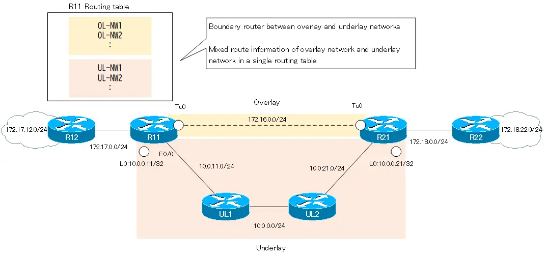
In other words, the routing of the overlay and underlay networks will be related to each other. A minor mistake in routing configuration can break the overlay network. Additional controls, such as route filters, are necessary for the overlay network to function properly.
In addition, address ranges for overlay and underlay networks cannot overlap. Address range overlap is also not allowed when building multiple overlay networks.
In the following sections, we will explain the problems with point-to-point GRE overlay networks that do not use FVRF with specific network diagram.
Example of GRE overlay network without FVRF
Network diagram
Consider the following network diagram.

Build an overlay network of point-to-point GRE tunnels between R11 and R12.
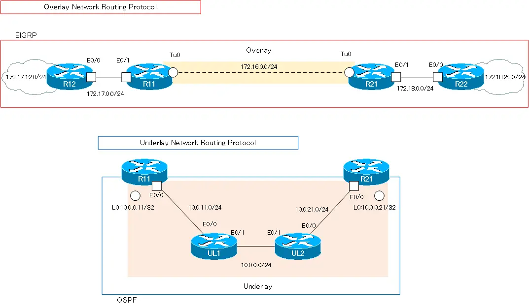
In addition, the address ranges of the overlay and underlay networks do not overlap. The overlay network is addressed with Class B private addresses such as 172.16.x.x and 172.17.x.x and 172.18.x.x. And the underlay network is addressing with 10.x.x.x class A private addresses.
In order to separate the overlay and underlay networks, routing protocols are separated. EIGRP is used in the overlay network and OSPF is used in the underlay network; no redistribution between EIGRP and OSPF is performed.
| Address range | Routing protocol | |
|---|---|---|
| Overlay network | 172.16.0.0/16 172.17.0.0/16 172.18.0.0/16 | EIGRP |
| Underlay network | 10.0.0.0/8 | OSPF |
Excerpts of configuration of each device
Here is an excerpt of the relevant configuration commands of each device. R11/R21 are the important ones.
R11 Configuration Excerpts (Click)
hostname R11
!
interface Loopback0
 ip address 10.0.0.11 255.255.255.255
!
interface Tunnel0
 ip address 172.16.0.11 255.255.255.0
 tunnel source Loopback0
 tunnel destination 10.0.0.21
!
interface Ethernet0/0
 ip address 10.0.11.11 255.255.255.0
!
interface Ethernet0/1
 ip address 172.17.0.11 255.255.255.0
!
router eigrp 1
 network 172.16.0.0
 network 172.17.0.0
 eigrp router-id 11.11.11.11
!
router ospf 1
 router-id 11.11.11.11
 network 10.0.0.11 0.0.0.0 area 0
 network 10.0.11.11 0.0.0.0 area 0
R21 Configuration Excerpts (Click)
hostname R21
!
interface Loopback0
 ip address 10.0.0.21 255.255.255.255
!
interface Tunnel0
 ip address 172.16.0.21 255.255.255.0
 tunnel source Loopback0
 tunnel destination 10.0.0.11
!
interface Ethernet0/0
 ip address 10.0.21.21 255.255.255.0
!
interface Ethernet0/1
 ip address 172.18.0.21 255.255.255.0
!
router eigrp 1
 network 172.16.0.0
 network 172.18.0.0
 eigrp router-id 21.21.21.21
!
router ospf 1
 router-id 21.21.21.21
 network 10.0.0.21 0.0.0.0 area 0
 network 10.0.21.21 0.0.0.0 area 0
R12 Configuration Excerpts (Click)
hostname R12
!
interface Loopback0
 ip address 172.17.12.12 255.255.255.0
 ip ospf network point-to-point
!
interface Ethernet0/0
 ip address 172.17.0.12 255.255.255.0
!
router eigrp 1
 network 172.17.0.0
 eigrp router-id 12.12.12.12
R22 Configuration Excerpts (Click)
hostname R22
!
interface Loopback0
 ip address 172.18.22.22 255.255.255.0
 ip ospf network point-to-point
!
interface Ethernet0/0
 ip address 172.18.0.22 255.255.255.0
!
router eigrp 1
 network 172.18.0.0
 eigrp router-id 22.22.22.22
UL1 Configuration Excerpts (Click)
hostname UL1
!
interface Ethernet0/0
 ip address 10.0.11.1 255.255.255.0
!
interface Ethernet0/1
 ip address 10.0.0.1 255.255.255.0
!
router ospf 1
 router-id 1.1.1.1
 network 10.0.0.0 0.255.255.255 area 0
UL2 Configuration Excerpts (Click)
hostname UL2
!
interface Ethernet0/0
 ip address 10.0.21.2 255.255.255.0
!
interface Ethernet0/1
 ip address 10.0.0.2 255.255.255.0
!
router ospf 1
 router-id 2.2.2.2
 network 10.0.0.0 0.255.255.255 area 0
Mixed overlay and underlay network route information
As mentioned earlier, without VRF, route information for overlay and underlay networks will be mixed; if we look at the routing table for R11, we find the following contents.
R11 Routing table
R11#show ip route | exclude L
-- omitted --

Gateway of last resort is not set

      10.0.0.0/8 is variably subnetted, 6 subnets, 2 masks
O        10.0.0.0/24 [110/20] via 10.0.11.1, 00:00:17, Ethernet0/0
C        10.0.0.11/32 is directly connected, Loopback0
O        10.0.0.21/32 [110/31] via 10.0.11.1, 00:00:07, Ethernet0/0
C        10.0.11.0/24 is directly connected, Ethernet0/0
O        10.0.21.0/24 [110/30] via 10.0.11.1, 00:00:17, Ethernet0/0
      172.16.0.0/16 is variably subnetted, 2 subnets, 2 masks
C        172.16.0.0/24 is directly connected, Tunnel0
      172.17.0.0/16 is variably subnetted, 3 subnets, 2 masks
C        172.17.0.0/24 is directly connected, Ethernet0/1
D        172.17.12.0/24 [90/409600] via 172.17.0.12, 00:01:02, Ethernet0/1
      172.18.0.0/24 is subnetted, 2 subnets
D        172.18.0.0 [90/26905600] via 172.16.0.21, 00:00:07, Tunnel0
D        172.18.22.0 [90/27033600] via 172.16.0.21, 00:00:07, Tunnel0
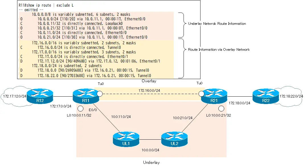
In the routing table of R11, route information for 10.x.x.x in the underlay network and “172.16.x.x”, “172.17.x.x” and “172.18.x.x” communicating via the overlay network have been mixed together. The same is true for R21.
Note that the routing protocols for the overlay and underlay networks are separated. And we do not redistribute. Therefore, routers other than R11/R21 do not mix overlay network route information with underlay network route information. the routing table for R12 is as follows.
R12 Routing table
R12#show ip route | exclude L
-- omitted --

Gateway of last resort is not set

      172.16.0.0/24 is subnetted, 1 subnets
D        172.16.0.0 [90/26905600] via 172.17.0.11, 00:11:23, Ethernet0/0
      172.17.0.0/16 is variably subnetted, 4 subnets, 2 masks
C        172.17.0.0/24 is directly connected, Ethernet0/0
      172.18.0.0/24 is subnetted, 2 subnets
D        172.18.0.0 [90/26931200] via 172.17.0.11, 00:11:22, Ethernet0/0
D        172.18.22.0 [90/27059200] via 172.17.0.11, 00:11:22, Ethernet0/0
Breaking the overlay network
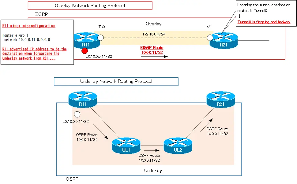
By separating the routing protocols, we are separating the overlay network from the underlay network. However, a minor misconfiguration of the routing protocol can easily break the overlay network.
Specifically, when Loopback0 of R11/R21, which is configured as tunnel destination, is advertised with EIGRP in the overlay network, the overlay network (GRE tunnel) is broken. Let’s advertise Loopback0 (10.0.0.11) on R11 with EIGRP. Note that Lo0 (10.0.0.11) in R11 is the destination IP address when forwarding over the underlay network from R21.
R11 Advertise Lo0 with EIGRP (break GRE tunnel)
router eigrp 1
 network 10.0.0.11 0.0.0.0
This alone will break the GRE tunnel between R11 and R21. We see a log of Tunnel0 repeating up/down on R21.
R21 Tunnel0 flapping
R21#
*Aug 29 01:51:09.218: %TUN-5-RECURDOWN: Tunnel0 temporarily disabled due to recursive routing
*Aug 29 01:51:09.218: %LINEPROTO-5-UPDOWN: Line protocol on Interface Tunnel0, changed state to down
*Aug 29 01:51:09.218: %DUAL-5-NBRCHANGE: EIGRP-IPv4 1: Neighbor 172.16.0.11 (Tunnel0) is down: interface down
R21#
*Aug 29 01:52:09.257: %LINEPROTO-5-UPDOWN: Line protocol on Interface Tunnel0, changed state to up
*Aug 29 01:52:10.212: %DUAL-5-NBRCHANGE: EIGRP-IPv4 1: Neighbor 172.16.0.11 (Tunnel0) is up: new adjacency
R21#
*Aug 29 01:52:10.535: %ADJ-5-PARENT: Midchain parent maintenance for IP midchain out of Tunnel0 - looped chain attempting to stack
R21#
If EIGRP is enabled on Lo0 of R11, R11 will advertise the EIGRP route 10.0.0.11/32 from Tunnel0.R21 receives OSPF route 10.0.0.11/32 and EIGRP route 10.0.0.11/32. EIGRP routes are preferred because of EIGRP’s lower administrative distance. Then R21 learns the route information needed to establish Tunnel0 via Tunnel0. As a result, R21 Tunnel0 is broken.
To prevent the GRE tunnel from being broken like this, the routing protocols for the overlay and underlay networks were separated. でA minor misconfiguration can break the overlay network of GRE tunnels. This can be prevented by not only separating routing protocols, but also by performing route filtering.
But …
Instead of having to do all sorts of controls within one routing process, we can just separate the VRFs!”
This is the point of FVRF.
Related article
See the following article on separating the overlay network of point-to-point GRE tunnels with VRFs.
Summary
Points
- If the GRE overlay network uses only the default routing process without VRF, route information for the overlay network will be mixed with route information for the underlay network.
- Various routing controls are needed to prevent the overlay network from being broken due to misconfiguration or other reasons.
Advanced IP Routing
- Overview of Cisco Route-map
- Cisco Route-map Configuration
- GRE Tunnel Interface – Virtual Point-to-Point Connection
- GRE Tunnel Interface Configuration Example
- Overview of VRF/VRF-Lite – Virtually separating the router –
- Cisco VRF Configuration and Verification Commands
- Cisco Layer 3 VPN with VRF-Lite Configuration Example
- What Is FVRF(Front door VRF)?
- Point-to-point GRE Tunnel without FVRF
- Point-to-point GRE tunnel with FVRF (tunnel vrf command)
- IPSec VTI with FVRF
- IPSec VTI with FVRF Configuration Example
- DMVPN with FVRF
- DMVPN with FVRF Configuration Example Part1
- DMVPN with FVRF Configuration Example Part2
