Table of Contents
Routing principles
Routers cannot forward data (IP packets) destined for networks that are not registered in the routing table and discard them.
Therefore, it is a prerequisite that the routing tables of all the routers on the network have the correct and complete route information for all the networks to which you want to forward data.
Configure static routes
Static route is a configuration method in which route information (network address/subnet mask, next hop) is registered by entering commands for each router. It is not possible to configure correctly unless you have a good grasp of the network that should be registered in the routing table for each router based on the overall image of the network. Also, the fact that communication is bi-directional must be taken into consideration when making configurations.
The commands for configuring static routes on Cisco routers are explained in the following article.
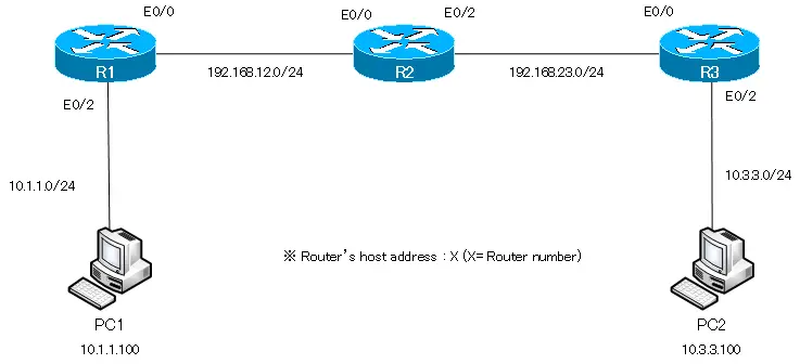
Network diagram
We will proceed step by step to configure a static route with the following simple network diagram. Even with a simple network diagram, communication will not be successful unless you properly consider the static route configuration.
Routing table when only IP addresses are configured.
When only IP addresses are configured in R1 to R3, only the route information about the directly connected network of each router is registered in the routing table.
R1
R1#show ip route
- ommitted -

Gateway of last resort is not set

C    192.168.12.0/24 is directly connected, Ethernet0/0
     10.0.0.0/24 is subnetted, 1 subnets
C       10.1.1.0 is directly connected, Ethernet0/2
R2
R2#show ip route
- ommitted -

Gateway of last resort is not set

C    192.168.12.0/24 is directly connected, Ethernet0/0
C    192.168.23.0/24 is directly connected, Ethernet0/2
R3
R3#show ip route
- ommitted -

Gateway of last resort is not set

     10.0.0.0/24 is subnetted, 1 subnets
C       10.3.3.0 is directly connected, Ethernet0/2
C    192.168.23.0/24 is directly connected, Ethernet0/0
From the routing table, we can see that the following four networks are interconnected by R1 to R3.
| Network address | Connecting router |
| 10.1.1.0/24 | R1 |
| 192.168.12.0/24 | R1/R2 |
| 192.168.23.0/24 | R2/R3 |
| 10.3.3.0/24 | R3 |
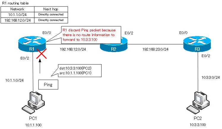
However, if the IP address are configured and only the route information of the directly connected network is in the routing table, data cannot be transferred between all networks. For example, a ping from PC1 (10.1.1.100) to PC2 (10.3.3.3) will not get a response.
ping from PC1 to PC2
PC1> ping 10.3.3.100
*10.1.1.1 icmp_seq=1 ttl=255 time=8.114 ms (ICMP type:3, code:1, Destination host unreachable)
*10.1.1.1 icmp_seq=2 ttl=255 time=8.081 ms (ICMP type:3, code:1, Destination host unreachable)
*10.1.1.1 icmp_seq=3 ttl=255 time=11.207 ms (ICMP type:3, code:1, Destination host unreachable)
*10.1.1.1 icmp_seq=4 ttl=255 time=4.270 ms (ICMP type:3, code:1, Destination host unreachable)
*10.1.1.1 icmp_seq=5 ttl=255 time=9.841 ms (ICMP type:3, code:1, Destination host unreachable)
An ICMP echo request for a ping from PC1 to PC2 will be discarded by R1 because R1 does not have the route information to forward to 10.3.3.3.
Configure static routes for communication between PC1 and PC2.
Configure a static route of 10.3.3.0/24 on R1.
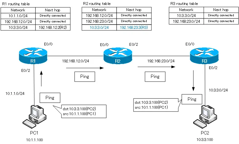
Configure a static route to communicate between PC1 and PC2. on R1, configure the route information for 10.3.3.0/24 with the following command. The next hop is R2, i.e. 192.168.12.2.
R1 static route for 10.3.3.0/24
ip route 10.3.3.0 255.255.255.0 192.168.12.2
After configuring the static route for 10.3.3.0/24, the routing table for R1 will look like the following
R1 routing table
R1#show ip route
-- ommitted --

Gateway of last resort is not set

C    192.168.12.0/24 is directly connected, Ethernet0/0
     10.0.0.0/24 is subnetted, 2 subnets
S       10.3.3.0 [1/0] via 192.168.12.2
C       10.1.1.0 is directly connected, Ethernet0/2
Pinging from PC1 to PC2 fails even if I configure a static route of 10.3.3.0/24 only on R1
ping from PC1 to PC2
PC1> ping 10.3.3.100
10.3.3.100 icmp_seq=1 timeout
10.3.3.100 icmp_seq=2 timeout
10.3.3.100 icmp_seq=3 timeout
10.3.3.100 icmp_seq=4 timeout
10.3.3.100 icmp_seq=5 timeout
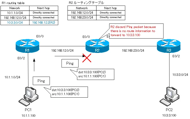
R1 is forwarding the ping from PC1 to PC2 to R2. But there is no route information matching the destination IP address 10.3.3.100 in R2, so the ping packet from PC1 to PC2 is discarded by R2.
Configure a static route of 10.3.3.0/24 on R2.
We need to configure a static route of 10.3.3.0/24 not only on R1 but also on R2, where the next hop is R3, i.e. 192.168.23.3.
R2 static route of 10.3.3.0/24
ip route 10.3.3.0 255.255.255.0 192.168.23.3
Verifying the routing table on R2, a static route of 10.3.3.0/24 is added.
R2 routing table
R2#show ip route
-- ommitted --

Gateway of last resort is not set

C    192.168.12.0/24 is directly connected, Ethernet0/0
     10.0.0.0/24 is subnetted, 1 subnets
S       10.3.3.0 [1/0] via 192.168.23.3
C    192.168.23.0/24 is directly connected, Ethernet0/2
However, even with a static route of 10.3.3.0/24 on R2, the ping from PC1 to PC2 does not succeed.
ping from PC1 to PC2
PC1> ping 10.3.3.100
10.3.3.100 icmp_seq=1 timeout
10.3.3.100 icmp_seq=2 timeout
10.3.3.100 icmp_seq=3 timeout
10.3.3.100 icmp_seq=4 timeout
10.3.3.100 icmp_seq=5 timeout
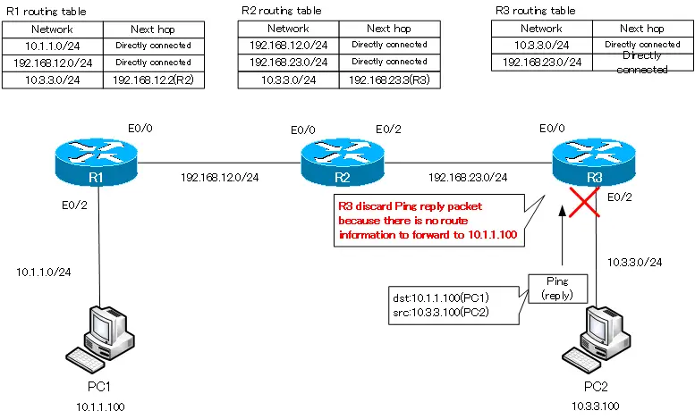
With a static route of 10.3.3.0/24 on R1 and R2, an ICMP echo request pinging from PC1 to PC2 is reaching PC2.
Don’t forget that communication is bi-directional: when PC1 pings PC2 and an ICMP echo request reaches PC2, it replies with an ICMP echo reply. The destination IP address and source IP address of the ICMP echo request are swapped in the ICMP echo reply. The destination is 10.1.1.100 (PC1) and the source is 10.3.3.100 (PC2). R3 has no route information matching the destination 10.1.1.100, so it discards it.
Configure a static route of 10.1.1.0/24 on R3.
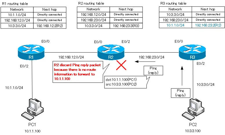
To enable PC2 to return a ping reply to PC1, configure R3 with a static route of 10.1.1.0/24 as the route information matching the destination 10.1.1.100.
R3 static route of 10.1.1.0/24
ip route 10.1.1.0 255.255.255.0 192.168.23.2
With this configuration, the static route 10.1.1.0/24 will be registered in the routing table of R3 as follows.
R3 routing table
R3#show ip route
-- ommitted --

Gateway of last resort is not set

     10.0.0.0/24 is subnetted, 2 subnets
C       10.3.3.0 is directly connected, Ethernet0/2
S       10.1.1.0 [1/0] via 192.168.23.2
C    192.168.23.0/24 is directly connected, Ethernet0/0
However, pinging from PC1 to PC2 is still not successful.
ping from PC1 to PC2
PC1> ping 10.3.3.100
10.3.3.100 icmp_seq=1 timeout
10.3.3.100 icmp_seq=2 timeout
10.3.3.100 icmp_seq=3 timeout
10.3.3.100 icmp_seq=4 timeout
10.3.3.100 icmp_seq=5 timeout
When we ping PC1 to PC2, the ICMP echo request is forwarded to PC2. Then, an ICMP echo reply is sent from PC2 to PC1 as a reply. The echo reply is forwarded from R3 to R2, but R2 has no route information matching the destination 10.1.1.100. The ICMP echo reply will be discarded by R2, so the ping will not succeed.
Configure a static route of 10.1.1.0/24 on R2.
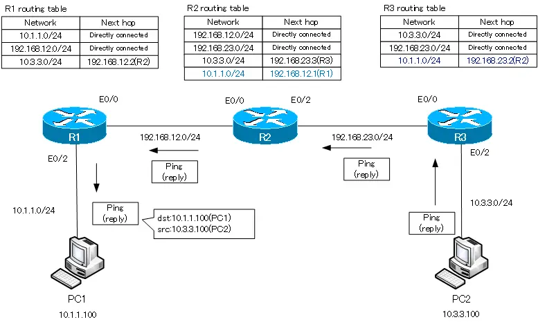
Configure a static route for 10.1.1.0/24 on R2 so that it can return an ICMP echo reply in response to an ICMP echo request for a ping from PC1 to PC2.
R2 static route of 10.1.1.0/24
ip route 10.1.1.0 255.255.255.0 192.168.12.1
The static route of 10.1.1.0/24 will be registered in the routing table of R2 as shown below.
R2 routing table
R2#show ip route
-- ommitted --

Gateway of last resort is not set

C    192.168.12.0/24 is directly connected, Ethernet0/0
     10.0.0.0/24 is subnetted, 2 subnets
S       10.3.3.0 [1/0] via 192.168.23.3
S       10.1.1.0 [1/0] via 192.168.12.1
C    192.168.23.0/24 is directly connected, Ethernet0/2
This will finally allow PC1 to successfully ping PC2.
ping from PC1 to PC2
PC1> ping 10.3.3.100
84 bytes from 10.3.3.100 icmp_seq=1 ttl=61 time=55.660 ms
84 bytes from 10.3.3.100 icmp_seq=2 ttl=61 time=63.150 ms
84 bytes from 10.3.3.100 icmp_seq=3 ttl=61 time=66.075 ms
84 bytes from 10.3.3.100 icmp_seq=4 ttl=61 time=57.319 ms
84 bytes from 10.3.3.100 icmp_seq=5 ttl=61 time=61.142 ms
Configure a Static Route for communication between R1 and R3
Can’t ping from R1 to R3…
With the static route configuration up to this point, communication between PC1 and PC2 is possible. However, pinging from R1 to R3 will fail.
ping form R1 to R3
R1#ping 192.168.23.3

Type escape sequence to abort.
Sending 5, 100-byte ICMP Echos to 192.168.23.3, timeout is 2 seconds:
.....
Success rate is 0 percent (0/5)
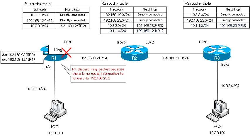
I am getting ping responses between PC1 and PC2, but I am not getting any ping responses between R1 and R3 on that route. If you can easily say, “That’s natural,” then you have the basic principle of routing at the beginning of this article firmly in your mind: when you ping from R1 to 192.168.23.3 on R3, the destination/source IP addresses are as follows
destination IP : 192.168.23.3
source IP : 192.168.12.2
The ICMP echo request for ping cannot be sent because there is no route information matching the destination IP address 192.168.23.3 in the routing table on R1.
Configure static route 192.168.23.0/24 on R1
To send an ICMP echo request for ping from R1 to R3 (192.168.23.3), add the route information of 192.168.23.0/24 to the routing table on R1.
R1 static route of 192.168.23.0/24
ip route 192.168.23.0 255.255.255.0 192.168.12.2
With this configuration, the static route of 192.168.23.0/24 will be registered in the routing table on R1.
R1 routing table
R1#show ip route
-- omitted --

Gateway of last resort is not set

C    192.168.12.0/24 is directly connected, Ethernet0/0
     10.0.0.0/24 is subnetted, 2 subnets
S       10.3.3.0 [1/0] via 192.168.12.2
C       10.1.1.0 is directly connected, Ethernet0/2
S    192.168.23.0/24 [1/0] via 192.168.12.2
If you just configure a static route of 192.168.23.0/24 on R1, the ping from R1 to R3 will still fail.
ping from R1 to R3
R1#ping 192.168.23.3

Type escape sequence to abort.
Sending 5, 100-byte ICMP Echos to 192.168.23.3, timeout is 2 seconds:
.....
Success rate is 0 percent (0/5)
By configuring a static route of 192.168.23.0/24 on R1, ICMP echo requests for ping from R1 to R3 are now forwarded.
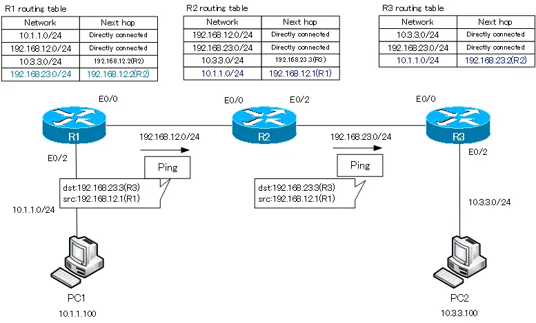
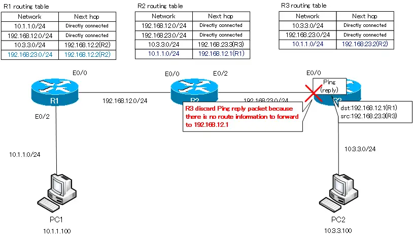
After all, we must not forget that communication is a two-way process. R3 returns an ICMP echo reply to R1 in response to a ping. The destination/source IP address is as follows
destination IP : 192.168.12.1
source IP : 192.168.23.3
Discard the IP packet destined to 192.168.12.1 because there is no route information in the routing table on R3 to forward it.
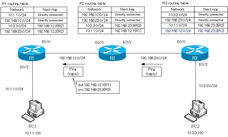
Configure static route 192.168.12.0/24 on R3
Configure R3 with a static route of 192.168.12.0/24 so that R3 can reply to pings.
R3 static route of 192.168.12.0/24
ip route 192.168.12.0 255.255.255.0 192.168.23.2
If you verify the routing table on R3, you will see the following
R3 routing table
R3#show ip route
-- ommitted --

Gateway of last resort is not set

S    192.168.12.0/24 [1/0] via 192.168.23.2
     10.0.0.0/24 is subnetted, 2 subnets
C       10.3.3.0 is directly connected, Ethernet0/2
S       10.1.1.0 [1/0] via 192.168.23.2
C    192.168.23.0/24 is directly connected, Ethernet0/0
This will finally allow pinging from R1 to R3 to succeed.
ping from R1 to R3
R1#ping 192.168.23.3

Type escape sequence to abort.
Sending 5, 100-byte ICMP Echos to 192.168.23.3, timeout is 2 seconds:
!!!!!
Success rate is 100 percent (5/5), round-trip min/avg/max = 60/67/92 ms
The final routing table
The final routing table for R1 to R3 will look like the following
R1 routing table
R1#show ip route
-- omitted --

Gateway of last resort is not set

C    192.168.12.0/24 is directly connected, Ethernet0/0
     10.0.0.0/24 is subnetted, 2 subnets
S       10.3.3.0 [1/0] via 192.168.12.2
C       10.1.1.0 is directly connected, Ethernet0/2
S    192.168.23.0/24 [1/0] via 192.168.12.2
R2 routing table
R2#show ip route
-- omitted --

Gateway of last resort is not set

C    192.168.12.0/24 is directly connected, Ethernet0/0
     10.0.0.0/24 is subnetted, 2 subnets
S       10.3.3.0 [1/0] via 192.168.23.3
S       10.1.1.0 [1/0] via 192.168.12.1
C    192.168.23.0/24 is directly connected, Ethernet0/2
R3 routing table
R3#show ip route
-- omitted --

Gateway of last resort is not set

S    192.168.12.0/24 [1/0] via 192.168.23.2
     10.0.0.0/24 is subnetted, 2 subnets
C       10.3.3.0 is directly connected, Ethernet0/2
S       10.1.1.0 [1/0] via 192.168.23.2
C    192.168.23.0/24 is directly connected, Ethernet0/0
Only when all the route information for the following four networks are registered in the routing table on R1 to R3, will communication between these four networks be possible.
- 10.1.1.0/24
- 10.3.3.0/24
- 192.168.12.0/24
- 192.168.23.0/24
When actually configuring static routes, there is of course no need to register them step by step like this. However, as the scale of the network grows and the number of routers and interconnected networks increases, you can imagine that the number of static routes to be configured will increase rapidly. Therefore, configuring the routing table with static routes is generally suitable for networks that are not very large.
IP Routing Basic
- Router – The central device that performs routing
- Dividing Network with router
- Layer3 Switch Overview
- Measuring the distance to the destination network -Administrative Distance and Metric
- Equal Cost Multi Path Load Balancing
- Cisco Static Route Configuration
- Example of Cisco Static Route Configuration Step by Step
- RIP Split horizon
- RIP Timers
- RIP Route Poisoning – Quickly remove unnecessary route information
- Cisco RIP Basic Configuration and Verification Commands
- Cisco RIP Configuration Example
- Generating a default route in RIP – Redistribution of static route
- Passive-Interface ~Stops Routing Protocols from Sending Packets
- Default Gateway Redundancy Overview
- How the Cisco HSRP works
- Configuring and Verifying Cisco HSRP
- How VRRP works
- Configuring and Verifying commands for VRRP [Cisco]
