Table of Contents
Summary
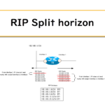
This is an example of RIP configuration on a Cisco router; in addition to the basic RIP configuration, we will check passive-interface, split-horizon disabling, and route poisoning.
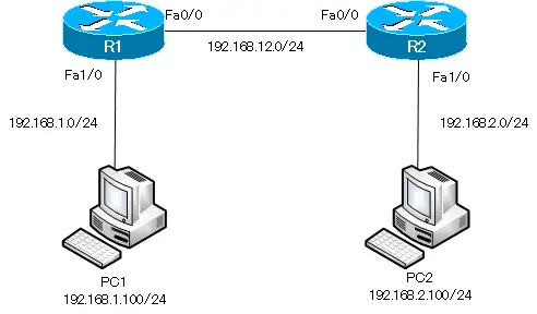
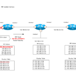
Network Diagram
Initial Configuration
- R1/R2
- Host name / IP address
- PC1/PC2
- Host name / IP address/ default gateway
Configuration Condition
- Build the routing table by RIPv2 on R1/R2.
- Do not send RIP route information from unnecessary interfaces.
- The RIP timer should be set to half the default value.
Configuration and Verification
Step1:Configure RIPv2
Enable RIPv2 on Fa0/0 and Fa1/0 of R1/R2. Also, disable auto-summarization with no auto-summary command.
R1
router rip
 network 192.168.1.0
 network 192.168.12.0
 version 2
 no auto-summary
R2
router rip
 network 192.168.2.0
 network 192.168.12.0
 version 2
 no auto-summary
Step2: Configure passive-interface
There is no need to send RIP route information from Fa1/0 where only PCs are connected. Configure Fa1/0 as a passive-interface on R1/R2.
R1/R2
router rip
 passive-interface FastEthernet1/0
Step3: Configure RIP timers
The default value of the RIP timer is as follows.
| Timer | default (sec) |
| Update | 30 |
| Invalid | 180 |
| Hold down | 180 |
| Flush | 240 |
Configure the timer value on R1/R2 as half of the default value.
R1/R2
router rip
 timers basic 15 90 90 120
Related article
For more information about RIP timers, please see the following article.
Step4: Verify RIP configuration
Verify the configurations from Step 1 to Step 3 with the show ip protocols command; the show ip protocols command on R1 is shown below.
R1
R1#show ip protocols
Routing Protocol is "rip"
  Outgoing update filter list for all interfaces is not set
  Incoming update filter list for all interfaces is not set
  Sending updates every 15 seconds, next due in 11 seconds
  Invalid after 90 seconds, hold down 90, flushed after 120
  Redistributing: rip
  Default version control: send version 2, receive version 2
    Interface             Send  Recv  Triggered RIP  Key-chain
    FastEthernet0/0       2     2
  Automatic network summarization is not in effect
  Maximum path: 4
  Routing for Networks:
    192.168.1.0
    192.168.12.0
  Passive Interface(s):
    FastEthernet1/0
  Routing Information Sources:
    Gateway         Distance      Last Update
    192.168.12.2         120      00:00:01
  Distance: (default is 120)
Also, verify the RIP route in the routing table; if you look at the routing table with the show ip route rip command on R1, you will see that 192.168.2.0/24 is registered.
R1
R1#show ip route rip
R    192.168.2.0/24 [120/1] via 192.168.12.2, 00:00:11, FastEthernet0/0
Step5: Communication Verification
If the RIP configurations on R1/R2 are correct, the necessary route information will be registered in the routing table. verify the RIP routes on R1/R2.
R1
R1#show ip route rip
R    192.168.2.0/24 [120/1] via 192.168.12.2, 00:00:07, FastEthernet0/0
R2
R2#show ip route rip
R    192.168.1.0/24 [120/1] via 192.168.12.1, 00:00:03, FastEthernet0/0
Now that the routing table has been successfully completed, communication between PC1 and PC2 is possible. ping from PC1 to PC2.
PC1
PC1> ping 192.168.2.100
84 bytes from 192.168.2.100 icmp_seq=1 ttl=62 time=39.652 ms
84 bytes from 192.168.2.100 icmp_seq=2 ttl=62 time=34.879 ms
84 bytes from 192.168.2.100 icmp_seq=3 ttl=62 time=35.262 ms
84 bytes from 192.168.2.100 icmp_seq=4 ttl=62 time=40.536 ms
84 bytes from 192.168.2.100 icmp_seq=5 ttl=62 time=38.431 ms
Step6: Verify that RIP routes are sent and received.
Verify that the RIP routes are being sent and received. run the show ip rip database command on R1 to verify the RIP database.
R1
R1#show ip rip database
192.168.1.0/24    auto-summary
192.168.1.0/24    directly connected, FastEthernet1/0
192.168.2.0/24    auto-summary
192.168.2.0/24
    [1] via 192.168.12.2, 00:00:01, FastEthernet0/0
192.168.12.0/24    auto-summary
192.168.12.0/24    directly connected, FastEthernet0/0
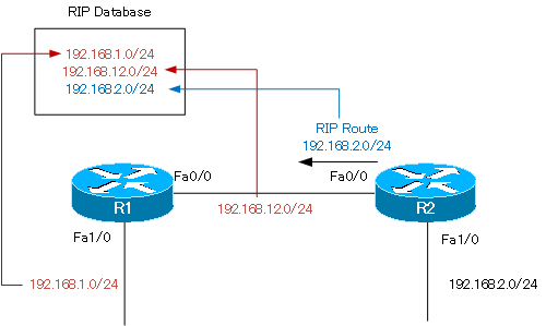
In the RIP database on R1, “192.168.1.0/24”, “192.168.12.0/24”, and “192.168.2.0/24” are registered. The two routes “192.168.1.0/24” and “192.168.12.0/24” are registered as RIP routes by R1 itself using the network command. “192.168.2.0/24” is a RIP route received from R2.
Then, enable debug ip rip on R1.
R1
R1#debug ip rip
RIP protocol debugging is on
R1#
*Mar  1 01:04:28.939: RIP: sending v2 update to 224.0.0.9 via FastEthernet0/0 (192.168.12.1)
*Mar  1 01:04:28.939: RIP: build update entries
*Mar  1 01:04:28.939:   192.168.1.0/24 via 0.0.0.0, metric 1, tag 0
R1#
*Mar  1 01:04:31.471: RIP: received v2 update from 192.168.12.2 on FastEthernet0/0
*Mar  1 01:04:31.471:      192.168.2.0/24 via 0.0.0.0 in 1 hops
R1#undebug all
All possible debugging has been turned off
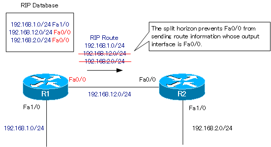
R1 is sending route information for 192.168.1.0/24 from Fa0/0. By split horizon, “192.168.12.0/24” and “192.168.2.0/24” are filtered out.
Step7: Disable Split Horizon
Disable split horizon on R1 Fa0/0.
R1
interface FastEthernet0/0
 no ip split-horizon
After disabling the split horizon, enter the debub ip rip command on R1 again to verify that RIP routes are being sent and received.
R1
R1#debug ip rip
RIP protocol debugging is on
R1#
*Mar  1 01:13:04.783: RIP: received v2 update from 192.168.12.2 on FastEthernet0/0
*Mar  1 01:13:04.783:      192.168.2.0/24 via 0.0.0.0 in 1 hops
R1#
*Mar  1 01:13:08.763: RIP: sending v2 update to 224.0.0.9 via FastEthernet0/0 (192.168.12.1)
*Mar  1 01:13:08.763: RIP: build update entries
*Mar  1 01:13:08.763:   192.168.1.0/24 via 0.0.0.0, metric 1, tag 0
*Mar  1 01:13:08.763:   192.168.2.0/24 via 192.168.12.2, metric 2, tag 0
*Mar  1 01:13:08.767:   192.168.12.0/24 via 0.0.0.0, metric 1, tag 0
R1#undebug all
All possible debugging has been turned off
When split horizon is disabled, the route information of “192.168.2.0/24” and “192.168.12.0/24” whose output interface is Fa0/0 will also be sent from Fa0/0.

After verifying that the route information is sent when split horizon is disabled, restore it.
R1
interface FastEthernet0/0
 ip split-horizon
Related article
For more information about Split Horizon, please see the following article.
Step8: Verify Route poisoning
Verify that the route information is promptly deleted by route poisoning. Shutdown Fa1/0 with debug ip rip enabled on R1.
R1
R1#debug ip rip
RIP protocol debugging is on
R1#configure terminal
Enter configuration commands, one per line.  End with CNTL/Z.
R1(config)#interface FastEthernet 1/0
R1(config-if)#shutdown
R1(config-if)#
*Mar  1 01:19:52.091: RIP: sending v2 flash update to 224.0.0.9 via FastEthernet0/0 (192.168.12.1)
*Mar  1 01:19:52.091: RIP: build flash update entries
*Mar  1 01:19:52.091:   192.168.1.0/24 via 0.0.0.0, metric 16, tag 0
*Mar  1 01:19:52.991: RIP: received v2 update from 192.168.12.2 on FastEthernet0/0
*Mar  1 01:19:52.991:      192.168.1.0/24 via 0.0.0.0 in 16 hops  (inaccessible)
R1(config-if)#
*Mar  1 01:19:53.083: %LINEPROTO-5-UPDOWN: Line protocol on Interface FastEthernet1/0, changed state to down
R1(config-if)#u
R1(config-if)#do undebug all
All possible debugging has been turned off
When the network of “192.168.1.0/24” goes down by shutting down Fa1/0 on R1, R1 is sending triggers updates.
*Mar 1 01:19:52.091: RIP: sending v2 flash update to 224.0.0.9 via FastEthernet0/0 (192.168.12.1)
Its content is that the metric for “192.168.1.0/24” is 16, meaning that 192.168.1.0/24 is down.
And we can see that Poison Reverse is being received from R2.
*Mar 1 01:19:52.991: 192.168.1.0/24 via 0.0.0.0 in 16 hops (inaccessible)
At this time, in the RIP database on R1, “192.168.1.0/24” is in the possibly down state.
R1
R1#show ip rip database
192.168.1.0/24 is possibly down
192.168.1.0/24 is possibly down
192.168.2.0/24    auto-summary
192.168.2.0/24
    [1] via 192.168.12.2, 00:00:09, FastEthernet0/0
192.168.12.0/24    auto-summary
192.168.12.0/24    directly connected, FastEthernet0/0
In the same way on the RIP database on R2, “192.168.1.0/24” is in the possibly down state, and the RIP route “192.168.1.0/24” has been deleted from the routing table.
R2
R2#show ip rip database
192.168.1.0/24 is possibly down
192.168.1.0/24 is possibly down
192.168.2.0/24    auto-summary
192.168.2.0/24    directly connected, FastEthernet1/0
192.168.12.0/24    auto-summary
192.168.12.0/24    directly connected, FastEthernet0/0
R2#show ip route rip
関連記事
Configuration Summary
Build the routing table by RIPv2 on R1/R2.
R1
router rip
 network 192.168.1.0
 network 192.168.12.0
 version 2
 no auto-summary
R2
router rip
 network 192.168.2.0
 network 192.168.12.0
 version 2
 no auto-summary
Do not send RIP route information from unnecessary interfaces.
R1/R2
router rip
 passive-interface FastEthernet1/0
The RIP timer should be set to half the default value.
R1/R2
router rip
 timers basic 15 90 90 120
IP Routing Basic
- Router – The central device that performs routing
- Dividing Network with router
- Layer3 Switch Overview
- Measuring the distance to the destination network -Administrative Distance and Metric
- Equal Cost Multi Path Load Balancing
- Cisco Static Route Configuration
- Example of Cisco Static Route Configuration Step by Step
- RIP Split horizon
- RIP Timers
- RIP Route Poisoning – Quickly remove unnecessary route information
- Cisco RIP Basic Configuration and Verification Commands
- Cisco RIP Configuration Example
- Generating a default route in RIP – Redistribution of static route
- Passive-Interface ~Stops Routing Protocols from Sending Packets
- Default Gateway Redundancy Overview
- How the Cisco HSRP works
- Configuring and Verifying Cisco HSRP
- How VRRP works
- Configuring and Verifying commands for VRRP [Cisco]