Table of Contents
The Role of Layer 3 Switches
Layer 3 switches can flexibly determine the network topology using VLAN, and are mainly used in corporate networks to interconnect multiple networks.
A Layer 3 switch is a network device that adds the functions of a router to a Layer 2 switch. Therefore, it can forward data like a layer 2 switch or like a router. The appearance of a Layer 3 switch is very similar to that of a Layer 2 switch. It is a network device with many Ethernet interfaces just like a Layer 2 switch.
The following table summarizes the characteristics of data transfer between Layer 2 switches and routers.
| Features | Layer2 Switch | Router |
| The data to be transferred | Ethernet Frame | IP Packet |
| Data transfer range | Within the same network | Between Networks |
| Tables to be referenced for transfer | MAC address table | Routing table |
| The address to be referenced for transfer | MAC address | IP address |
| What to do when the table does not have the necessary information | Flooding data | Discarding data |
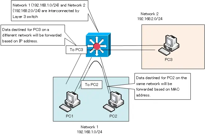
Layer 3 switches can interconnect networks in the same way as routers. And when transferring data in the same network, it is based on the MAC address, just like a layer 2 switch. On the other hand, when transferring data between networks, data is transferred based on IP addresses, just like a router.

In this figure, the layer 3 switch interconnects network 1 (192.168.1.0/24) and network 2 (192.168.2.0/24). And PC1 and PC2 are on the same network, while PC3 is on a different network. In order to configure such a network, the VLAN (Virtual LAN) function is used in the Layer 3 switch. To understand how Layer 3 switches work, it is essential to understand VLAN.
Understanding VLAN is very important to understand how Layer 3 switches work.
The detailed mechanism of VLAN is summarized in the following link.
Layer 3 Switch Application
Layer 3 switches are often used to interconnect multiple networks in a company’s internal network to enable communication between networks. In other words, it is mainly used as a router rather than as a layer 2 switch.
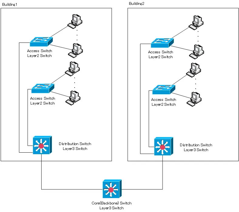
Most corporate internal networks consist of a Layer 2 switch and a Layer 3 switch. Client PCs on the office floor are first connected to the Layer 2 switch. The layer 2 switch, which corresponds to the entrance to the network, is called the “access switch”.
Then, Layer 3 switches are used to aggregate the Layer 2 switches on the floor. The Layer 3 switches allow communication between the networks on the floor. The Layer 3 switch that aggregates the access switches on the floor is called a “distribution switch”.
An access switch and a distribution switch constitute a single building network. In a large scale internal network, there will be multiple buildings on the site. Naturally, the networks of the buildings must also be interconnected. Layer 3 switches are also used to interconnect the building networks. The Layer 3 switches used for interconnecting the networks of these buildings are called “core switches” or “backbone switches”.

When the scale of the system becomes large to some extent, the Layer 3 switches of the distribution switches and core switches will be redundant. The above figure does not consider redundant Layer 3 switches for simplicity.
Layer 3 Switch ≒ Router
Layer 3 switches are used in the same way as routers, so it is safe to assume that Layer 3 switches ≒ routers. In a nutshell, the following are the differences in features between a router and a Layer 3 Switch.
| Features | Router | Layer3 Switch |
| Interface type | Various interfaces are available in addition to Ethernet. | Basically, Ethernet only |
| Number of interfaces | It doesn’t have that many interfaces. | Some products have more than a few hundred interfaces. |
| Scalability | Functionality can be expanded with software updates. | Not very extensible. |
| Data transfer performance | Not very high. | Maximum theoretical transfer performance can be achieved. |
However, today, the differences in features between routers and Layer 3 switches summarized in this table are almost non-existent.
Depending on the product, more and more Layer 3 switches can be equipped with interfaces other than Ethernet. In most cases, the Ethernet interface alone is sufficient, so the type of interface supported is not really an issue. The number of routers with many Ethernet interfaces is also increasing.
Even Layer 3 switches are becoming capable of expanding their functionality later with software updates. Also, the data transfer performance of routers is getting higher and higher, and there are many products that can provide the maximum theoretical transfer performance.
As mentioned earlier, “routers” and “layer 3 switches” are classified as types of network equipment, but nowadays it is safe to assume that they are almost the same.
IP Routing Basic
- Router – The central device that performs routing
- Dividing Network with router
- Layer3 Switch Overview
- Measuring the distance to the destination network -Administrative Distance and Metric
- Equal Cost Multi Path Load Balancing
- Cisco Static Route Configuration
- Example of Cisco Static Route Configuration Step by Step
- RIP Split horizon
- RIP Timers
- RIP Route Poisoning – Quickly remove unnecessary route information
- Cisco RIP Basic Configuration and Verification Commands
- Cisco RIP Configuration Example
- Generating a default route in RIP – Redistribution of static route
- Passive-Interface ~Stops Routing Protocols from Sending Packets
- Default Gateway Redundancy Overview
- How the Cisco HSRP works
- Configuring and Verifying Cisco HSRP
- How VRRP works
- Configuring and Verifying commands for VRRP [Cisco]
