Table of Contents
Role of the Router
Routers are network devices that interconnect multiple networks and transfer data between networks. A company’s internal network is made up of multiple networks for each department and so on. Routers are used to interconnect these multiple networks. Not only corporate internal networks, but also the Internet has a huge number of networks, which are interconnected by routers.
Routers then forward the data between the interconnected networks. Data transfer between networks by routers is called “routing”. Also, for routers, data is IP packets; IP is a network layer protocol in the OSI reference model, and since routers are network devices that forward IP packets, they are network devices at the network layer level of the OSI reference model.
Connect the network by configuring the IP address.
Connecting the network means configuring the IP address. A router connecting multiple networks is also a matter of configuring IP addresses for the router’s interfaces. For a router to interconnect networks, in addition to physically wiring the router’s interfaces, it also configures the interfaces with IP addresses. For example, if the physical wiring of router interface 1 is done, the interface is enabled, and the IP address 192.168.1.254/24 is configured, then router interface 1 is connected to the 192.168.1.0/24 network. A router is equipped with multiple interfaces, and by physically wiring each interface and configuring the IP address, the router will interconnect multiple networks.
When you configure an IP address on a router interface, you are connecting a network
R1 in the figure has three interfaces. By physically wiring interface 1 and configuring the IP address 192.168.1.254/24, interface 1 of router 1 is connected to network 1, 192.168.1.0/24. Similarly, by configuring IP addresses for interface 2 and interface 3, R1 is interconnecting network 1, network 2, and network 3.
Network 3 is connected not only to R1 but also to R2, and by physically wiring and configuring IP addresses for R2’s three interfaces in the same way as R1, R2 interconnects Network 3, Network 4, and Network 5.
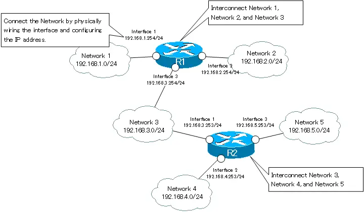
Figure Network interconnection with router.
Routing Overview
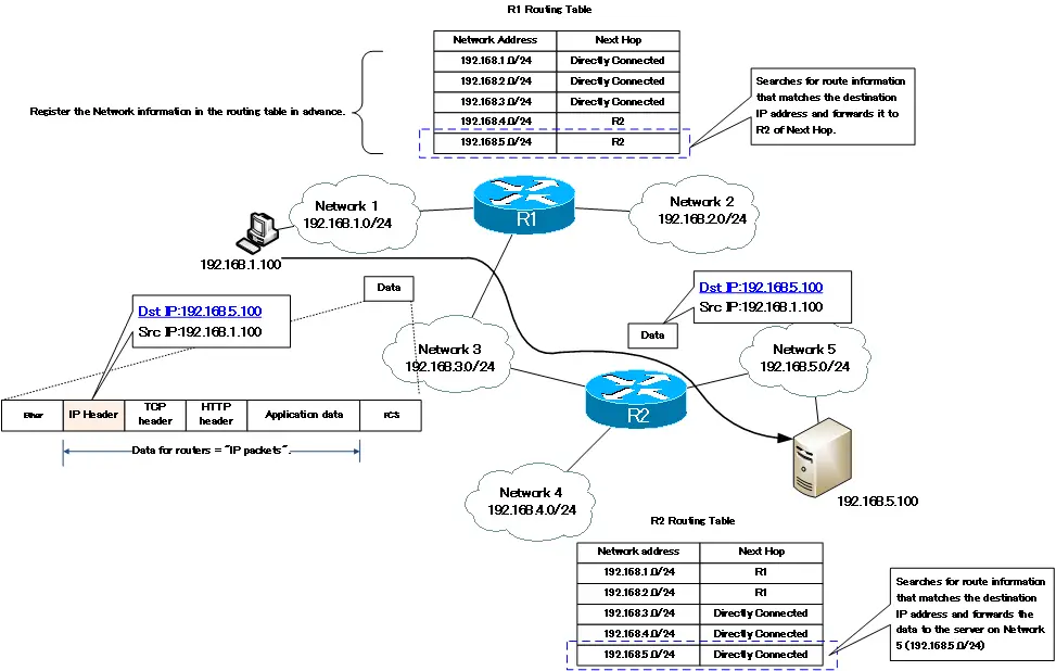
Routers forward data (IP packets) to the appropriate network based on IP addresses. However, in order to do so, the router needs to have the information of the destination network registered in its routing table beforehand. In order to perform routing, the first prerequisite is to create a routing table for the router.
When an IP packet arrives at a router, the router determines the next router (next hop) to be forwarded based on the destination IP address written in the IP header and the routing table, and forwards the IP packet. IP packets destined for networks that are not registered in the routing table cannot be forwarded and will be discarded. Registering network information in the routing table is a very important aspect of routing. This point is very different from the operation of a Layer 2 switch. Layer 2 switches work by “flooding if not known”. A router, on the other hand, acts as a “discard if not known”.
Routers can’t forward packets to unknown networks.
The difference in data forwarding behavior between Layer 2 switches and routers can be considered to be due to the difference in forwarding range. The forwarding range of a Layer 2 switch is only within the same network. For now, flooding will not have a significant impact. Routers, on the other hand, transfer data between networks. If the router doesn’t know the destination but forwards the data anyway, there is a big possibility that unnecessary data transfer will occur frequently.
R1 and R2 in the following figure need to register the information of all the networks they want to forward IP packets to in their routing table. In this figure, there are five networks, from network 1 (192.168.1.0/24) to network 5 (192.168.5.0/24). Then, when transferring data from the host (192.168.1.100) to the server (192.168.5.100), the destination IP address will be 192.168.5.100. RR1 searches for information about the network on the routing table that matches the destination IP address. Then, since the next hop is R2, R1 will forward IP packets to R2.A “hop” often refers to a router, and the next hop is the router that should be forwarded next.
Then, R2 also looks at the destination IP address and routing table indicated in the IP packet and forwards the IP packet to the server on the directly connected network 5 (192.168.5.0/24).
In this diagram, only the one-way case is shown, but please remember again that communication is, in principle, bidirectional. In order for the server to return a reply to the client PC, the router on the route must be able to route it correctly.
IP Routing Basic
- Router – The central device that performs routing
- Dividing Network with router
- Layer3 Switch Overview
- Measuring the distance to the destination network -Administrative Distance and Metric
- Equal Cost Multi Path Load Balancing
- Cisco Static Route Configuration
- Example of Cisco Static Route Configuration Step by Step
- RIP Split horizon
- RIP Timers
- RIP Route Poisoning – Quickly remove unnecessary route information
- Cisco RIP Basic Configuration and Verification Commands
- Cisco RIP Configuration Example
- Generating a default route in RIP – Redistribution of static route
- Passive-Interface ~Stops Routing Protocols from Sending Packets
- Default Gateway Redundancy Overview
- How the Cisco HSRP works
- Configuring and Verifying Cisco HSRP
- How VRRP works
- Configuring and Verifying commands for VRRP [Cisco]
