
Table of Contents
Overview
Separate the overlay network of point-to-point GRE tunnels from the underlay network with VRF. In addition, it is necessary to associate the overlay and underlay networks. The tunnel vrf command is the configuration command for this purpose.
Related articles
The following article provides an overview of FVRF.
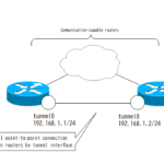
The GRE tunnel interface is described in the following article.
FVRF and IVRF
Handling overlay and underlay networks in a single global routing process requires different route controls. VRF is used to build a more stable overlay network.
- FVRF(Front door VRF)
- IVRF(Inside VRF)
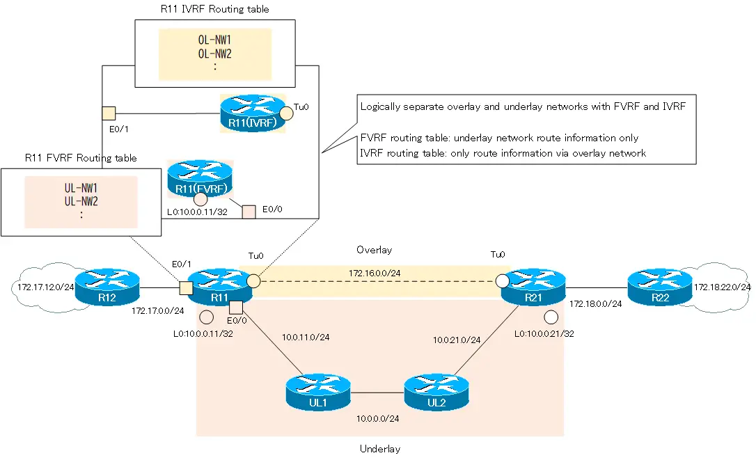
FVRF is configured as VRF for underlay network. And IVRF is configured as VRF for overlay network.
The overlay network can use the global routing process (default VRF) instead of VRF.
Only route information via the overlay network is registered in the routing table of IVRF. And in the routing table of FVRF, only the route information of the underlay network is registered.
tunnel vrf command
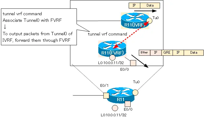
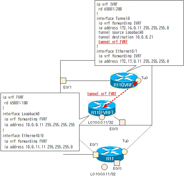
Now consider when packets are output from IVRF’s Tunnle0 interface.
Packets output from Tunnel0 (IVRF) are actually forwarded through the underlay network (FVRF). For this purpose, a GRE header and a new IP header for forwarding over the underlay network (FVRF) will be added. However, there is no FVRF route information in the IVRF routing table. This means that a new IP header cannot be added to forward over the underlay network.
When a packet is output from Tunnel 0 of IVRF, it needs to be associated with FVRF, which will actually forward the packet. The tunnel vrf command associates the FVRF for output packets from the Tunnel interface of the IVRF.
The format of the tunnel vrf command is as follows
tunnel vrf command
(config)#interface tunnel <interface-number>
(config-if)#tunnel vrf <fvrf-name>
<interface-number> : Tunnel interface number
<fvrf-name> : FVRF name to be associated
Based on the VRF routing table associated with the tunnel vrf command, the reachability of the tunnel destination IP address will be viewed. The VRF associated with the tunnel vrf command can be verified with the show ip interface tunnel command.
show ip interface tunnel
R11#show ip int tunnel 0
Tunnel0 is up, line protocol is up
  Internet address is 172.16.0.11/24
  Broadcast address is 255.255.255.255
  Address determined by non-volatile memory
  MTU is 1476 bytes
-- omitted --
  VPN Routing/Forwarding "IVRF"
  Downstream VPN Routing/Forwarding ""
  Tunnel VPN Routing/Forwarding "FVRF"
-- omitted --
Point-to-point GRE tunnel with FVRF configuration example
Network Diagram
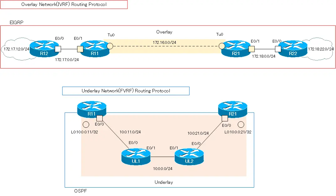
Consider the following network diagram. This is the same network diagram as “Point-to-point GRE Tunnel without FVRF“.

Build an overlay network of point-to-point GRE tunnels between R11 and R12. Then, separate the overlay network from the underlay network with VRF; as VRF, configure the following
| Router | VRF name | RD | Interface |
|---|---|---|---|
| R11 | FVRF | 65001:100 | Lo0 Eth0/0 |
| IVRF | 65001:200 | Tunnel0 Eth0/1 | |
| R21 | FVRF | 65001:100 | Lo0 Eth0/0 |
| IVRF | 65001:200 | Tunnel0 Eth0/1 |
In addition, the address ranges of IVRF in the overlay network and FVRF in the underlay network do not overlap. IVRF is addressing with Class B private addresses such as 172.16.x.x and 172.17.x.x and 172.18.x.x. And FVRF is addressing with class A private addresses of 10.x.x.x.
As routing protocols, IVRF uses EIGRP and FVRF uses OSPF.
| Address Range | Routing Protocol | |
|---|---|---|
| Overlay Network(IVRF) | 172.16.0.0/16 172.17.0.0/16 172.18.0.0/16 | EIGRP |
| Underlay Network(FVRF) | 10.0.0.0/8 | OSPF |
Initial Configuration
The configuration is made from the state of no separation to FVRF/IVRF. Here is an excerpt of the initial configuration for each device.
R11 Configuration Excerpts(Click)
hostname R11
!
interface Loopback0
 ip address 10.0.0.11 255.255.255.255
!
interface Tunnel0
 ip address 172.16.0.11 255.255.255.0
 tunnel source Loopback0
 tunnel destination 10.0.0.21
!
interface Ethernet0/0
 ip address 10.0.11.11 255.255.255.0
!
interface Ethernet0/1
 ip address 172.17.0.11 255.255.255.0
!
router eigrp 1
 network 172.16.0.0
 network 172.17.0.0
 eigrp router-id 11.11.11.11
!
router ospf 1
 router-id 11.11.11.11
 network 10.0.0.11 0.0.0.0 area 0
 network 10.0.11.11 0.0.0.0 area 0
R21 Configuration Excerpts (Click)
hostname R21
!
interface Loopback0
 ip address 10.0.0.21 255.255.255.255
!
interface Tunnel0
 ip address 172.16.0.21 255.255.255.0
 tunnel source Loopback0
 tunnel destination 10.0.0.11
!
interface Ethernet0/0
 ip address 10.0.21.21 255.255.255.0
!
interface Ethernet0/1
 ip address 172.18.0.21 255.255.255.0
!
router eigrp 1
 network 172.16.0.0
 network 172.18.0.0
 eigrp router-id 21.21.21.21
!
router ospf 1
 router-id 21.21.21.21
 network 10.0.0.21 0.0.0.0 area 0
 network 10.0.21.21 0.0.0.0 area 0
R12 Configuration Excerpts (Click)
hostname R12
!
interface Loopback0
 ip address 172.17.12.12 255.255.255.0
 ip ospf network point-to-point
!
interface Ethernet0/0
 ip address 172.17.0.12 255.255.255.0
!
router eigrp 1
 network 172.17.0.0
 eigrp router-id 12.12.12.12
R22 Configuration Excerpts (Click)
hostname R22
!
interface Loopback0
 ip address 172.18.22.22 255.255.255.0
 ip ospf network point-to-point
!
interface Ethernet0/0
 ip address 172.18.0.22 255.255.255.0
!
router eigrp 1
 network 172.18.0.0
 eigrp router-id 22.22.22.22
UL1 Configuration Excerpts (Click)
hostname UL1
!
interface Ethernet0/0
 ip address 10.0.11.1 255.255.255.0
!
interface Ethernet0/1
 ip address 10.0.0.1 255.255.255.0
!
router ospf 1
 router-id 1.1.1.1
 network 10.0.0.0 0.255.255.255 area 0
UL2 Configuration Excerpts (Click)
hostname UL2
!
interface Ethernet0/0
 ip address 10.0.21.2 255.255.255.0
!
interface Ethernet0/1
 ip address 10.0.0.2 255.255.255.0
!
router ospf 1
 router-id 2.2.2.2
 network 10.0.0.0 0.255.255.255 area 0
Configuration and Verification
Step1: Create VRF and assign interfaces
Separate the overlay and underlay networks with VRF on R11/R21 at the boundary of the overlay and underlay networks. create VRF and assign interfaces.
R11 Create VRF and assign interfaces
ip vrf FVRF
 rd 65001:100
!
ip vrf IVRF
 rd 65001:200
!
interface Loopback0
 ip vrf forwarding FVRF
 ip address 10.0.0.11 255.255.255.255
!
interface Tunnel0
 ip vrf forwarding IVRF
 ip address 172.16.0.11 255.255.255.0
!
interface Ethernet0/0
 ip vrf forwarding FVRF
 ip address 10.0.11.11 255.255.255.0
!
interface Ethernet0/1
 ip vrf forwarding IVRF
 ip address 172.17.0.11 255.255.255.0
R21 Create VRF and assign interfaces
ip vrf FVRF
 rd 65100:100
!
ip vrf IVRF
 rd 65100:200
!
interface Loopback0
 ip vrf forwarding FVRF
 ip address 10.0.0.21 255.255.255.255
!
interface Tunnel0
 ip vrf forwarding IVRF
 ip address 172.16.0.21 255.255.255.0
!
interface Ethernet0/0
 ip vrf forwarding FVRF
 ip address 10.0.21.21 255.255.255.0
!
interface Ethernet0/1
 ip vrf forwarding IVRF
 ip address 172.18.0.21 255.255.255.0
Step2: Verify VRF creation and interface assignment
Verify the created VRFs and interface assignments with the show ip vrf command; on R11, the display looks like this.
R11 show ip vrf
R11#show ip vrf
  Name                             Default RD            Interfaces
  FVRF                             65001:100             Lo0
                                                         Et0/0
  IVRF                             65001:200             Tu0
                                                         Et0/1
However, the Tunnel0 interface is up/down.
R11 show interface tunnel0/show ip interface tunnel0
R11#show interface tunnel 0
Tunnel0 is up, line protocol is down
  Hardware is Tunnel
  Internet address is 172.16.0.11/24
  MTU 17916 bytes, BW 100 Kbit/sec, DLY 50000 usec,
     reliability 255/255, txload 1/255, rxload 1/255
  Encapsulation TUNNEL, loopback not set
  Keepalive not set
  Tunnel linestate evaluation down - no output interface
  Tunnel source 10.0.0.11 (Loopback0), destination 10.0.0.21
   Tunnel Subblocks:
      src-track:
         Tunnel0 source tracking subblock associated with Loopback0
          Set of tunnels with source Loopback0, 1 member (includes iterators), on interface
  Tunnel protocol/transport GRE/IP
    Key disabled, sequencing disabled
    Checksumming of packets disabled
-- omitted --
R11#show ip interface tunnel 0
Tunnel0 is up, line protocol is down
  Internet address is 172.16.0.11/24
  Broadcast address is 255.255.255.255
  Address determined by non-volatile memory
  MTU is 1476 bytes
  Helper address is not set
  Directed broadcast forwarding is disabled
  Multicast reserved groups joined: 224.0.0.10
-- omitted --
  VPN Routing/Forwarding "IVRF"
  Downstream VPN Routing/Forwarding ""
-- omitted --
This is because there is no connectivity to the tunnel destination 10.0.0.21. The default is to verify connectivity to the tunnel destination in the global routing table.
Step3: Configure tunnel vrf command
Configure the tunnel vrf command so that when packets are output from IVRF’s tunnel0, they can be forwarded through FVRF.
R11/R21 tunnel vrf
interface tunnel0
 tunnel vrf FVRF
Step4: Verify tunnel vrf command
With the tunnel vrf command, tunnel0 is now associated with the FVRF of the underlay network. But still tunnel0 is up/down.
R11 show ip interface tunnel0
R11#show ip int tunnel 0
Tunnel0 is up, line protocol is down
  Internet address is 172.16.0.11/24
  Broadcast address is 255.255.255.255
  Address determined by non-volatile memory
  MTU is 1476 bytes
  Helper address is not set
  Directed broadcast forwarding is disabled
  Multicast reserved groups joined: 224.0.0.10
~省略~
  VPN Routing/Forwarding "IVRF"
  Downstream VPN Routing/Forwarding ""
  Tunnel VPN Routing/Forwarding "FVRF"
~省略~
Tunnel0 is still in up/down state because there is no route to tunnel destination 10.0.0.21 in the FVRF routing table.
R11 show ip route vrf FVRF
R11#show ip route vrf FVRF

Routing Table: FVRF
~省略~

Gateway of last resort is not set

      10.0.0.0/8 is variably subnetted, 3 subnets, 2 masks
C        10.0.0.11/32 is directly connected, Loopback0
C        10.0.11.0/24 is directly connected, Ethernet0/0
L        10.0.11.11/32 is directly connected, Ethernet0/0
FVRF routing table is built up to ensure reachability to the tunnel destination.
Step5: Configure Routing per VRF
Once R11/R21 is separated into VRFs, you must also configure routing for each VRF. the routing configuration for FVRF is as follows: FVRF uses OSPF.
R11 FVRF Routing configuration(OSPF)
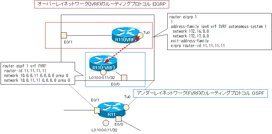
no router ospf 1
router ospf 1 vrf FVRF
 router-id 11.11.11.11
 network 10.0.0.11 0.0.0.0 area 0
 network 10.0.11.11 0.0.0.0 area 0
R21 FVRF Routing configuration(OSPF)
no router ospf 1
router ospf 1 vrf FVRF
 router-id 21.21.21.21
 network 10.0.0.21 0.0.0.0 area 0
 network 10.0.21.21 0.0.0.0 area 0
Then, IVRF uses EIGRP for routing.
R11 IVRF Routing configuration(EIGRP)
no router eigrp 1
router eigrp 1
 !
 address-family ipv4 vrf IVRF autonomous-system 1
  network 172.16.0.0
  network 172.17.0.0
 exit-address-family
 eigrp router-id 11.11.11.11
R21 IVRF Routing configuration(EIGRP)
no router eigrp 1
router eigrp 1
 !
 address-family ipv4 vrf IVRF autonomous-system 1
  network 172.16.0.0
  network 172.18.0.0
 exit-address-family
 eigrp router-id 21.21.21.21
The following figure summarizes the routing protocols for each VRF on R11.
Step6: Verify routing per VRF
Once the routing protocols for FVRF/IVRF are correctly configured, the routing table for each VRF is built. The routing table on R11 is as follows
R11 per VRF routing table
R11#show ip route vrf FVRF

Routing Table: FVRF
-- omitted --

Gateway of last resort is not set

      10.0.0.0/8 is variably subnetted, 6 subnets, 2 masks
O        10.0.0.0/24 [110/20] via 10.0.11.1, 00:08:40, Ethernet0/0
C        10.0.0.11/32 is directly connected, Loopback0
O        10.0.0.21/32 [110/31] via 10.0.11.1, 00:08:40, Ethernet0/0
C        10.0.11.0/24 is directly connected, Ethernet0/0
L        10.0.11.11/32 is directly connected, Ethernet0/0
O        10.0.21.0/24 [110/30] via 10.0.11.1, 00:08:40, Ethernet0/0
R11#show ip route vrf IVRF

Routing Table: IVRF
-- omitted --


Gateway of last resort is not set

      172.16.0.0/16 is variably subnetted, 2 subnets, 2 masks
C        172.16.0.0/24 is directly connected, Tunnel0
L        172.16.0.11/32 is directly connected, Tunnel0
      172.17.0.0/16 is variably subnetted, 3 subnets, 2 masks
C        172.17.0.0/24 is directly connected, Ethernet0/1
L        172.17.0.11/32 is directly connected, Ethernet0/1
D        172.17.12.0/24 [90/409600] via 172.17.0.12, 00:59:47, Ethernet0/1
      172.18.0.0/24 is subnetted, 2 subnets
D        172.18.0.0 [90/26905600] via 172.16.0.21, 00:08:43, Tunnel0
D        172.18.22.0 [90/27033600] via 172.16.0.21, 00:08:43, Tunnel0
Thus, on R11, the underlay and overlay networks are separated by VRF.
This completes all configuration for separating underlay and overlay networks in FVRF/IVRF.
Step7: Communication Verification
Verify that the overlay network can communicate properly; ping from R12 to R22.
Ping from R12 to R22
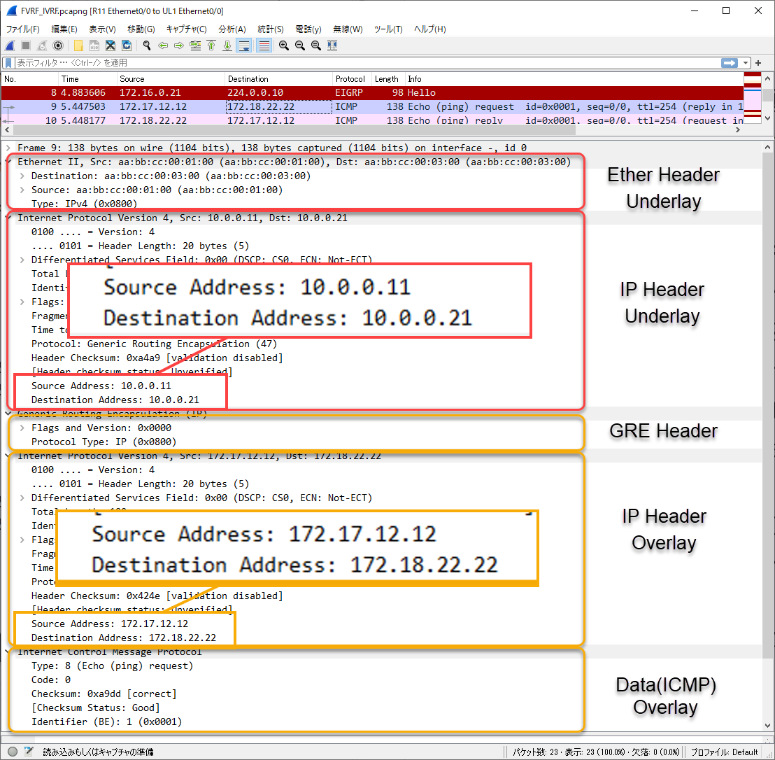
R12#ping 172.18.22.22 source 172.17.12.12
Type escape sequence to abort.
Sending 5, 100-byte ICMP Echos to 172.18.22.22, timeout is 2 seconds:
Packet sent with a source address of 172.17.12.12
!!!!!
Success rate is 100 percent (5/5), round-trip min/avg/max = 1/1/2 ms
The overlay network communication is working properly.
Capturing a ping from R12 to R22 on R11 E0/1, the contents are as follows.
Configuration command summary
This is a summary of the configuration commands configured on R11/R21 from the initial configuration.
R11 Configuration command summary
ip vrf FVRF
 rd 65001:100
!
ip vrf IVRF
 rd 65001:200
!
interface Loopback0
 ip vrf forwarding FVRF
 ip address 10.0.0.11 255.255.255.255
!
interface Tunnel0
 ip vrf forwarding IVRF
 ip address 172.16.0.11 255.255.255.0
 tunnel vrf FVRF
!
interface Ethernet0/0
 ip vrf forwarding FVRF
 ip address 10.0.11.11 255.255.255.0
!
interface Ethernet0/1
 ip vrf forwarding IVRF
 ip address 172.17.0.11 255.255.255.0
!
router eigrp 1
 !
 address-family ipv4 vrf IVRF autonomous-system 1
  network 172.16.0.0
  network 172.17.0.0
 exit-address-family
 eigrp router-id 11.11.11.11
!
router ospf 1 vrf FVRF
 router-id 11.11.11.11
 network 10.0.0.11 0.0.0.0 area 0
 network 10.0.11.11 0.0.0.0 area 0
R21 Configuration command summary
ip vrf FVRF
 rd 65100:100
!
ip vrf IVRF
 rd 65100:200
!
interface Loopback0
 ip vrf forwarding FVRF
 ip address 10.0.0.21 255.255.255.255
!
interface Tunnel0
 ip vrf forwarding IVRF
 ip address 172.16.0.21 255.255.255.0
 tunnel vrf FVRF
!
interface Ethernet0/0
 ip vrf forwarding FVRF
 ip address 10.0.21.21 255.255.255.0
!
interface Ethernet0/1
 ip vrf forwarding IVRF
 ip address 172.18.0.21 255.255.255.0
!
router eigrp 1
 !
 address-family ipv4 vrf IVRF autonomous-system 1
  network 172.16.0.0
  network 172.18.0.0
 exit-address-family
 eigrp router-id 21.21.21.21
!
router ospf 1 vrf FVRF
 router-id 21.21.21.21
 network 10.0.0.21 0.0.0.0 area 0
 network 10.0.21.21 0.0.0.0 area 0
Summary
Points
- Separate FVRF (Front door VRF) for underlay network and IVRF (Inside VRF) for overlay network to build a more stable overlay network.
- Use the tunnel vrf command to associate the IVRF Tunnel interface with FVRF.
Advanced IP Routing
- Overview of Cisco Route-map
- Cisco Route-map Configuration
- GRE Tunnel Interface – Virtual Point-to-Point Connection
- GRE Tunnel Interface Configuration Example
- Overview of VRF/VRF-Lite – Virtually separating the router –
- Cisco VRF Configuration and Verification Commands
- Cisco Layer 3 VPN with VRF-Lite Configuration Example
- What Is FVRF(Front door VRF)?
- Point-to-point GRE Tunnel without FVRF
- Point-to-point GRE tunnel with FVRF (tunnel vrf command)
- IPSec VTI with FVRF
- IPSec VTI with FVRF Configuration Example
- DMVPN with FVRF
- DMVPN with FVRF Configuration Example Part1
- DMVPN with FVRF Configuration Example Part2