Table of Contents
Configuring Layer3 Switch
To configure the Layer 3 switch, first enable IP routing by entering the ip routing command in global configuration mode.
Then, by configuring IP addresses on Layer 3 switches, VLANs (networks) are interconnected to enable communication between VLANs. The IP address configuration of a Layer 3 switch can be done in one of the following ways
- Configuring SVI
- Configuring routed port
Configuring SVI
The SVI is a virtual interface that connects the internal router to the VLAN. Configure an IP address for the SVI to connect the VLAN to the internal router. Enter the following command in global configuration mode.
(config)#interface vlan <vlan-id>
(config-if)#ip address <address> <subnetmask>
<vlan-id> : VLAN ID
<address> : IP address
<subnetmask> : subnetmask
Configuring routed port
A routed port is a port that is directly connected to an internal router. By configuring the port of the Layer 3 switch as a routed port and configuring the IP address, the Layer 3 switch will connect the network. The routed port configuration is as follows
(config)#interface <interface-name>
(config-if)#no switchport
(config-if)#ip address <address> <subnetmask>
<interface-name> : interface-name to be routed port
<address> : IP address
<subnetmask> : subnetmask
In both SVI and routed port configurations, when an IP address is configured and the interface becomes up, the Directly connected route information according to the IP address will be registered in the routing table.
Configuration example of Layer3 switch
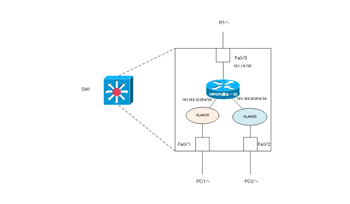
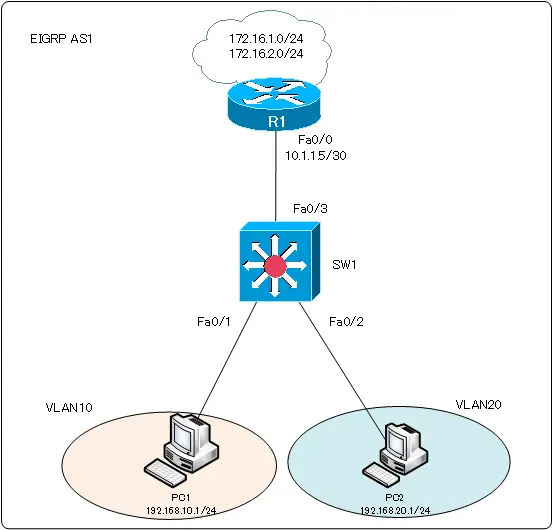
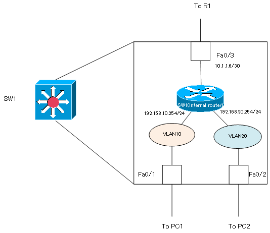
In the network diagram shown in the following figure, configure SW1: SW1 Fa0/3 is configured as a routed port. Then, create SVIs on the internal router to interconnect VLAN10 and VLAN20.
SW1
ip routing
!
interface FastEthernet0/3
 no switchport
 ip address 10.1.1.6 255.255.255.252
!
interface Vlan10
 ip address 192.168.10.254 255.255.255.0
 no shutdown
!
interface Vlan20
 ip address 192.168.20.254 255.255.255.0
 no shutdown
With this configuration, the internal router, VLAN, and port of SW1 will be connected as follows
On SW1, the output of the show ip interface brief command and the show ip route command is displayed as shown below.
SW1
SW1#show ip interface brief
Interface                  IP-Address      OK? Method Status                Protocol
FastEthernet0/1            unassigned      YES unset  up                    up
FastEthernet0/2            unassigned      YES unset  up                    up
FastEthernet0/3            10.1.1.6        YES manual up                    up
- omitted -
Vlan10                     192.168.10.254  YES manual up                    up
Vlan20                     192.168.20.254  YES manual up                    up
SW1#show ip route
- omitted -

Gateway of last resort is not set

C    192.168.10.0/24 is directly connected, Vlan10
C    192.168.20.0/24 is directly connected, Vlan20
     10.0.0.0/30 is subnetted, 1 subnets
C       10.1.1.4 is directly connected, FastEthernet0/3
VLAN(Virtual LAN)
- The need to divide the network
- Details of dividing the network
- VLAN Overview
- VLAN behavior
- Access port : Port assigned to only one VLAN
- Trunk port : Port assigned to multiple VLANs
- Summary of Trunk Protocols – IEEE802.1Q and ISL
- Native VLAN
- Specific example of native VLAN mismatch
- Cisco DTP
- Cisco Configuring and Verifying VLAN
- Cisco VLAN Detailed Configuration Example
- Notes on deleting VLANs
- Voice VLAN – VLAN for connecting IP phones
- VTP :Synchronize VLAN configuration
- VTP pruning – Stopping unnecessary flooding of trunk links
- Configuring and Verifying Cisco VTP
- Inter VLAN routing overview
- Inter-VLAN routing by router
- Inter-VLAN routing by Layer 3 switch
- Configuring and Verifying Inter-VLAN Routing by Cisco Router
- Cisco Configuring Inter-VLAN routing by Layer3 switch : SVI/routed port
- Cisco Layer3 Switch Basic Configuration Example
- Summary of Layer 3 Switch Port Concepts – Access Port/Trunk Port/SVI/Routed Port
- LAN Design pattern : 2-tier and 3-tier