
Table of Contents
How to divide the network
VLAN is a technology used by Layer 2 switches to divide a network. To understand more about VLAN, let’s consider in detail about dividing a network. The following methods can be used to divide a network.
- Physically divided.
- Logically divided
- Divide by IP address configuration(network layer)
- Divide by VLAN configuration(datalink layer)
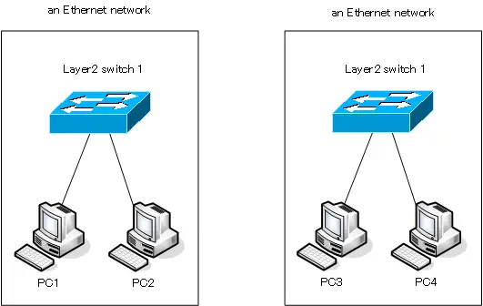
Physically divide the Ethernet network
Physically dividing an Ethernet network is very easy. We just separate the Layer 2 switches.
A Layer 2 switch creates a “single Ethernet network”. Therefore, two Layer 2 switches will give you two Ethernet networks.
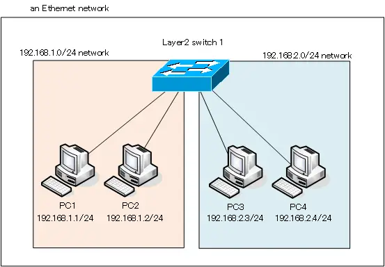
Divide the network by IP address configuration
In order to perform TCP/IP communication, you need to configure TCP/IP configuration such as IP address/subnet mask. By configuring the IP address, it is possible to divide the network even if the PCs are physically connected to the same Ethernet network.
If four PCs, PC1 to PC4, are connected to a single Layer 2 switch, PC1 to PC4 are on physically the same Ethernet network.
If you configure the IP address of PCs as follows, you can logically divide the network into “192.168.1.0/24 network” and “192.168.2.0/24 network”.
PC1:192.168.1.1/24
PC2:192.168.1.2/24
PC3:192.168.2.3/24
PC4:192.168.2.4/24
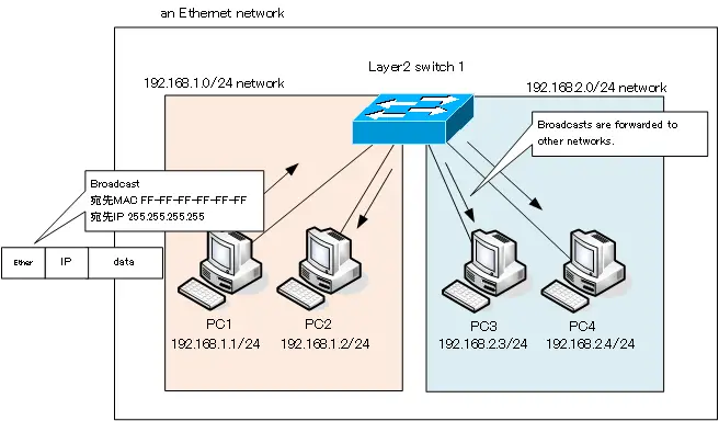
However, if the network is physically one Ethernet network in this way, broadcast/multicast, etc. will be flooded. If PC1 sends a broadcast, it will reach PC3 or PC4 on different network than PC1. if broadcast reaches PC3 or PC4, it will most likely be discarded without being processed. But it is not desirable to have extra broadcasts/multicasts, etc.
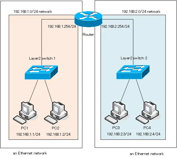
Physically divide and also divide by IP address configuration
To divide the network, physically divide the Ethernet network, and then logically divide it by configuring the IP address. If we think about it in terms of the OSI reference model hierarchy, a network is divided at the physical layer and then further divided at the network layer.
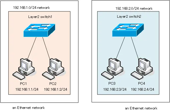
Until the advent of VLAN, network was physically divided into separate switches in this way, and then logically divided by IP address configuration. When a network is divided, communication with other networks is not possible. In the network diagram we have mentioned so far, communication from PC1/PC2 to PC3 or PC4 will not be possible. Since we don’t want that, we will interconnect the divided networks with router.
Divide the network by VLAN
If you physically prepare separate Layer 2 switches and divide the Ethernet network, you will need a lot of Layer 2 switches. VLAN allow an Ethernet network to be efficiently partitioned using a single Layer 2 switch. The following figure shows an example of dividing an Ethernet network with VLAN.
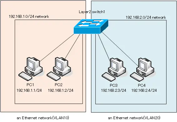
VLAN10 and VLAN20 are configured on Layer 2 Switch 1. The port to which PC1/PC2 is connected is assigned to VLAN10, and the port to which PC3/PC4 is connected is assigned to VLAN20. Then Layer 2 Switch 1 divides the network into two parts, an Ethernet network with VLAN 10 and an Ethernet network with VLAN 20.PC1 to PC4 are configured with IP addresses so that PC1/PC2 are on the same 192.168.1.0/24 network and PC3/PC4 are on 192.168.2.0/24.
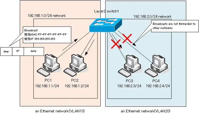
When an Ethernet network is divided by VLAN, broadcasts/multicasts, etc. do not flow to other network (VLAN). They will be forwarded only within the same network.
For more information on how VLAN are used to divide networks, please see the following article.
VLAN(Virtual LAN)
- The need to divide the network
- Details of dividing the network
- VLAN Overview
- VLAN behavior
- Access port : Port assigned to only one VLAN
- Trunk port : Port assigned to multiple VLANs
- Summary of Trunk Protocols – IEEE802.1Q and ISL
- Native VLAN
- Specific example of native VLAN mismatch
- Cisco DTP
- Cisco Configuring and Verifying VLAN
- Cisco VLAN Detailed Configuration Example
- Notes on deleting VLANs
- Voice VLAN – VLAN for connecting IP phones
- VTP :Synchronize VLAN configuration
- VTP pruning – Stopping unnecessary flooding of trunk links
- Configuring and Verifying Cisco VTP
- Inter VLAN routing overview
- Inter-VLAN routing by router
- Inter-VLAN routing by Layer 3 switch
- Configuring and Verifying Inter-VLAN Routing by Cisco Router
- Cisco Configuring Inter-VLAN routing by Layer3 switch : SVI/routed port
- Cisco Layer3 Switch Basic Configuration Example
- Summary of Layer 3 Switch Port Concepts – Access Port/Trunk Port/SVI/Routed Port
- LAN Design pattern : 2-tier and 3-tier