Table of Contents
Switch port types
In order to have a clear understanding of how VLANs work, it is important to be aware of how VLANs and ports are assigned inside the switch. Depending on how the VLANs and ports are assigned inside the Layer 2 switch, the ports of the switch can be divided into two types as follows
- Access port
- Trunk port
An access port is a port that is assigned to only one VLAN. It can forward only Ethernet frames of the VLAN to which it is assigned. On the other hand, a trunk port is a port that is assigned to multiple VLANs and can forward Ethernet frames of multiple VLANs.
Access ports and trunk ports are sometimes referred to collectively as “switch port”. In contrast to Layer 3 switch ports, the term “switch port” should be considered to refer to ports as Layer 2 switches.
This page provides a detailed explanation of trunk ports.
Important points for Layer 2 switch ports
- Be aware of VLAN and port assignments properly.
- Access ports are ports that are assigned to only one VLAN.
- Trunk ports are ports that are assigned to multiple VLANs.
Related article
For more information about access port, please see the following article.
Trunk port
A network will often be implemented using multiple switches, rather than just one. Then, you may want to implement VLANs across the switches. In that case, you will have to forward Ethernet frames of multiple VLANs between switches. When implementing multiple VLANs across switches, trunk ports are used to simplify the connection between switches.
VLAN across switches
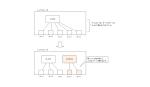
Let’s think specifically about VLAN across switches. To simplify the discussion, the following diagram considers the case where two VLANs, VLAN10 and VLAN20, are configured across two Layer 2 switches.
VLANs allow Layer 2 switches to forward Ethernet frames only between ports of the same VLAN. Therefore, to configure VLAN 10 across two Layer 2 switches, you only need to connect the Layer 2 switches with the ports assigned to VLAN 10.
Similarly, to configure VLAN 20 on two Layer 2 switches, connect them on the port that is assigned to VLAN 20.

If you connect between Layer 2 switches for each VLAN in this way, you can configure VLANs across switches. However, this type of connection between switches is not efficient. The more VLANs, the more ports are used on the switch, and adding more VLANs later requires not only a change in the switch configuration but also additional physical wiring. So, we can connect the switches with trunk ports.
Connection between switches by trunk port
A port on a Layer 2 switch can be configured as a trunk port. When configuring multiple VLANs across switches, a trunk port allows only one connection between switches. A trunk port is a port that is assigned to multiple VLANs and can forward Ethernet frames of multiple VLANs. Then, VLAN tags are added to the Ethernet frames sent and received on the trunk port.
The basic mechanism of VLANs is to “forward Ethernet frames only between ports of the same VLAN”, as we have mentioned before. A switch knows its own internal VLAN and port assignments, but not the internal VLAN and port assignments of other switches.
Although L2SW1 in the following figure knows its own VLAN and port assignment, it does not know the VLAN and port assignment of L2SW2. Therefore, it does not know which VLAN the Ethernet frame forwarded from L2SW2 belongs to.

This is where the VLAN tag comes in. VLAN tags are added to Ethernet frames forwarded on trunk ports so that Ethernet frames forwarded between switches can be identified as belonging to which VLAN they originally belong. Ethernet frames are then forwarded only between ports of the same VLAN, which is the basic mechanism of VLANs, even if they span multiple switches.
IEEE802.1Q VLAN tag
The VLAN tag is specified in IEEE802.1Q, and IEEE802.1Q, which adds the VLAN tag, is called the trunk protocol. The Ethernet frame handled by the trunk port has the VLAN tag added to the header as shown in the figure below.
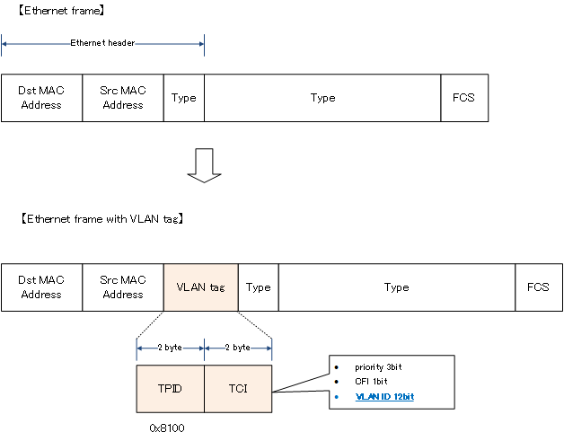
When a VLAN tag is added, the Ethernet header is changed. Therefore, the FCS will also be recalculated.
関連記事
There is an exception, native VLAN, which does not add a VLAN tag to Ethernet frames forwarded on a trunk port. Please see the following article about native VLANs.
Forwarding Ethernet frames on trunk ports
Instead of the network diagram shown in “Figure Connecting switches per VLAN”, we will consider Ethernet frame forwarding in a network diagram where switches are connected by trunk ports. By using a trunk port, only one link (port 8) needs to be connected between L2SW1 and L2SW2. When port 8 of L2SW1 and L2SW2 is configured as a trunk port, port 8 can be assigned to both VLAN10 and VLAN20, so Ethernet frames of both VLAN10 and VLAN20 can be forwarded.
When an Ethernet frame is sent from PC1 to PC3 in VLAN 10, it is received at port 1 of L2SW1. Port 1 is assigned to VLAN 10; the Ethernet frame received on VLAN 10 can be forwarded to trunk port 8, which is also assigned to VLAN 10. Then, when the Ethernet frame is forwarded from port 8, a VLAN tag is added to indicate that it is an Ethernet frame of VLAN 10.
When an Ethernet frame with a tag is received on port 8 of L2SW2, it is identified as VLAN 10 from the tag. Therefore, L2SW2 forwards the Ethernet frame to port 1, which is also a port of VLAN 10. At this time, the VLAN tag is removed and the frame becomes the original Ethernet frame.
In this way, Ethernet frames can be forwarded across the two Layer 2 switches L2SW1 and L2SW2 from PC1 to PC3 in the same VLAN10, and the same applies to PC2 and PC4 in VLAN20.
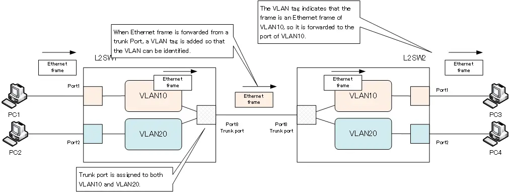
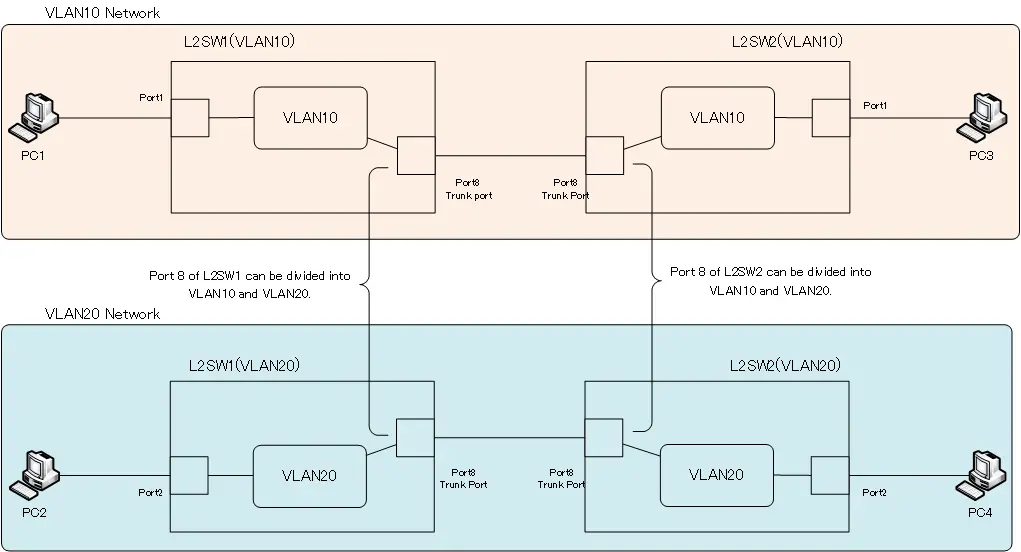
A simple way to think of a trunk port is that it is a port that can be divided into different VLANs that are assigned to it. If we make port 8 a trunk port and assign it to VLAN 10 and VLAN 20, port 8 will be divided into two.
Since switches can be divided by VLANs, and ports can be divided per VLAN by trunk ports, the network diagram we have been considering can be replaced by the following network diagram.
VLAN(Virtual LAN)
- The need to divide the network
- Details of dividing the network
- VLAN Overview
- VLAN behavior
- Access port : Port assigned to only one VLAN
- Trunk port : Port assigned to multiple VLANs
- Summary of Trunk Protocols – IEEE802.1Q and ISL
- Native VLAN
- Specific example of native VLAN mismatch
- Cisco DTP
- Cisco Configuring and Verifying VLAN
- Cisco VLAN Detailed Configuration Example
- Notes on deleting VLANs
- Voice VLAN – VLAN for connecting IP phones
- VTP :Synchronize VLAN configuration
- VTP pruning – Stopping unnecessary flooding of trunk links
- Configuring and Verifying Cisco VTP
- Inter VLAN routing overview
- Inter-VLAN routing by router
- Inter-VLAN routing by Layer 3 switch
- Configuring and Verifying Inter-VLAN Routing by Cisco Router
- Cisco Configuring Inter-VLAN routing by Layer3 switch : SVI/routed port
- Cisco Layer3 Switch Basic Configuration Example
- Summary of Layer 3 Switch Port Concepts – Access Port/Trunk Port/SVI/Routed Port
- LAN Design pattern : 2-tier and 3-tier
