Table of Contents
Configuring inter-VLAN routing by router
To configure a router and a Layer 2 switch for inter-VLAN routing by connecting them with a trunk, do the following on each router and switch.
- Switch
- Configure the port connected to the router as a trunk port.
- Router
- Create a sub-interface corresponding to the VLAN created on the switch
- Configure an IP address corresponding to the VLAN on the sub-interface.
- Configure static routes and routing protocols as needed.
Switch configuration
Dynamic negotiation by DTP (Dynamic Trunking Protocol) cannot be performed between routers and switches. Therefore, to perform inter-VLAN routing, you need to configure a port on the switch as a static trunk port. To make a port on the switch a static trunk port, configure it as follows
(config-if)#switchport trunk encapsulation {dot1q | isl}
(config-if)#switchport mode trunk
(config-if)#switchport nonegotiate
Router configuration
To create a sub-interface on a router, configure it in global configuration mode as follows
(config)#interface <type> <slot>/<port>.<subif-num>
(config-subif)#
<subif-num> : sub interface number
You can use any sub-interface number , but we often use the corresponding VLAN number to make the configuration easier to understand. Then, to enable trunking on a sub-interface and map VLANs, configure as follows.
(config-subif)#encapsulation {dot1q | isl} <vlan-id> [native]
<vlan-id> : VLAN number associated with the sub-interface
native : Specify as native VLAN
In order to perform IP routing, the sub-interface must have an IP address. The command to configure an IP address for a sub-interface is the same as the one for a normal interface.
(config-subif)#ip address <address> <subnetmask>
For example, let’s connect FastEthernet0/0 to the switch and create a sub-interface corresponding to VLAN1 as an IEEE802.1Q trunk. Then, to configure the sub-interface with the IP address 192.168.1.1/24, enter the following command
(config)#interface FastEthernet 0/0.1
(config-subif)#encapsulation dot1q 1
(config-subif)#ip address 192.168.1.1 255.255.255.0
If you configure an IP address for a sub-interface, the network address will be placed in the routing table as Directly Connected. This means that the VLAN network is now connected by the router.
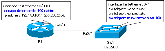
In the case of IEEE802.1Q trunks, native VLANs may also be configured. When Ethernet frames in the native VLAN are forwarded to the trunk, no VLAN tag is attached. The native VLANs must match on the opposite side. This means that the native VLAN must be configured on the router side to match the native VLAN on the trunk port on the switch side. To associate a sub-interface on the router with the native VLAN, configure it as follows
(config-subif)#encapsulation dot1q <vlan-num> native
The figure below shows an example configuration for matching native VLANs on a router and a switch.
For more information on native VLANs, please see the following articles
Configuration example of inter-VLAN routing using routers
In the network diagram below, consider the following example of inter-VLAN routing between a switch and a router.
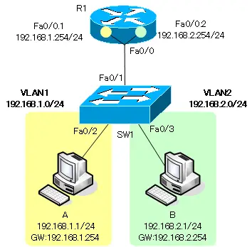
SW1 configuration
The SW1 configuration is as follows: configure the access port configuration for the interface to which the host is connected and the trunk port configuration for the interface to which the router is connected.
SW1
vlan 2
!
interface fastethernet 0/2
 switchport mode access
 switchport access vlan 1
 switchport nonegotiate
!
interface fastethernet 0/3
 switchport mode access
 switchport access vlan 2
 switchport nonegotiate
!
interface fastethernet 0/1
 switchport mode trunk
 switchport nonegotiate
R1 configuration
To configure R1, create a sub-interface corresponding to the VLAN and assign an IP address as follows
R1
interface FastEthernet 0/0.1
 encapsulation dot1q 1 native
 ip address 192.168.1.254 255.255.255.0
!
interface FastEthernet 0/0.2
 encapsulation dot1q 2
 ip address 192.168.2.254 255.255.255.0
Verify the configuration of inter-VLAN routing by routers.
To verify the configuration of inter-VLAN routing by the router, use the show command as shown in the following table for each device.
|
show command |
Details to be verified |
|
show vlan brief |
Verify that the VLAN membership of the interface to which host is connected is correct. |
|
show interface trunk |
Verify that the interface to which the router is connected is correctly configured as a trunk port. |
|
show command |
Details to be verified |
|
show ip interface brief |
Verify the IP address and stats of the router’s sub-interface; to verify not only the IP address but also the subnet mask, use the show ip interface command. |
|
show vlans |
Verify the association between the router’s subinterfaces and VLANs. |
|
show ip protocols |
Verify the summary information of the routing protocol. |
|
show ip route |
Verify the routing table of the router. The network address of the sub-interface will be Directly Connected. Also, if necessary, verify that static and dynamic routes are correctly present. |
We will also verify that end-to-end communication is actually possible by ping and traceroute. The sample output of the show command for the network diagram seen in the configuration example is as follows
SW1 verification
SW1
SW1#show vlan brief

VLAN Name                             Status    Ports
---- -------------------------------- --------- -------------------------------
1    default                          active    Fa0/2
2    VLAN0002                         active    Fa0/3
1002 fddi-default                     act/unsup
1003 token-ring-default               act/unsup
1004 fddinet-default                  act/unsup
1005 trnet-default                    act/unsup
SW1#show interfaces trunk

Port        Mode         Encapsulation  Status        Native vlan
Fa0/1       on           802.1q         trunking      1

Port      Vlans allowed on trunk
Fa0/1       1-4094

Port        Vlans allowed and active in management domain
Fa0/1       1-2

Port        Vlans in spanning tree forwarding state and not pruned
Fa0/1       1-2
R1 verification
R1
R1#show ip interafaces brief
Interface                  IP-Address      OK? Method Status                Protocol
FastEthernet0/0            unassigned      YES unset  up                    up
FastEthernet0/0.1          192.168.1.254   YES manual up                    up
FastEthernet0/0.2          192.168.2.254   YES manual up                    up
Serial0/0                  unassigned      YES unset  administratively down down
FastEthernet0/1            unassigned      YES unset  administratively down down
Serial0/1                  unassigned      YES unset  administratively down down
R1#show ip protocols

R1#show ip route
~省略~

Gateway of last resort is not set

C    192.168.1.0/24 is directly connected, FastEthernet0/0.1
C    192.168.2.0/24 is directly connected, FastEthernet0/0.2
R1#show vlans

Virtual LAN ID:  1 (IEEE 802.1Q Encapsulation)

   vLAN Trunk Interface:   FastEthernet0/0.1

 This is configured as native Vlan for the following interface(s) :
FastEthernet0/0

   Protocols Configured:   Address:              Received:        Transmitted:
           IP              192.168.1.254             1950                   0

Virtual LAN ID:  2 (IEEE 802.1Q Encapsulation)

   vLAN Trunk Interface:   FastEthernet0/0.2

   Protocols Configured:   Address:              Received:        Transmitted:
           IP              192.168.2.254                0                   0
VLAN(Virtual LAN)
- The need to divide the network
- Details of dividing the network
- VLAN Overview
- VLAN behavior
- Access port : Port assigned to only one VLAN
- Trunk port : Port assigned to multiple VLANs
- Summary of Trunk Protocols – IEEE802.1Q and ISL
- Native VLAN
- Specific example of native VLAN mismatch
- Cisco DTP
- Cisco Configuring and Verifying VLAN
- Cisco VLAN Detailed Configuration Example
- Notes on deleting VLANs
- Voice VLAN – VLAN for connecting IP phones
- VTP :Synchronize VLAN configuration
- VTP pruning – Stopping unnecessary flooding of trunk links
- Configuring and Verifying Cisco VTP
- Inter VLAN routing overview
- Inter-VLAN routing by router
- Inter-VLAN routing by Layer 3 switch
- Configuring and Verifying Inter-VLAN Routing by Cisco Router
- Cisco Configuring Inter-VLAN routing by Layer3 switch : SVI/routed port
- Cisco Layer3 Switch Basic Configuration Example
- Summary of Layer 3 Switch Port Concepts – Access Port/Trunk Port/SVI/Routed Port
- LAN Design pattern : 2-tier and 3-tier
