Table of Contents
Summary
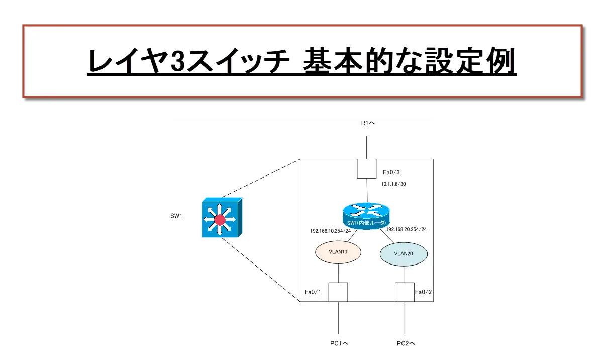
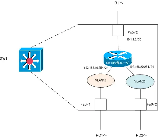
On a Layer 3 switch, configure IP addresses on the SVI/routed ports to interconnect the network (VLAN). Then, enable EIGRP so that it can exchange route information with other routers.
Network Diagram

Configuration Conditions
- SW1 Fa0/3, which is directly connected to R1, is used as a routed port; Fa0/1 and Fa0/2 are used as switch ports.
- The IP address for VLAN10 and VLAN20 of SW1 is the largest IP address in the subnet. the IP address of Fa0/3 is configured based on the IP address that can be configured.
- Configure EIGRP AS1 so that it can perform IP routing in the network diagram.
Initial Configuration
- Hostname
- IP address
R1 Fa0/0 - VTP domain,VLAN
SW1 VTP domain「SWITCH」, VTP transparent
VLAN10 and VLAN20 already created in SW1 - Routing protocol
EIGRP configuration required for R1 is complete.
Configuration
【Step1:Access port assignment】
SW1 Fa0/1 and Fa0/2 are switch ports. Configure the access port since they are assigned to a single VLAN: SW1 Fa0/1 as the access port for VLAN10 and SW1 Fa0/2 as the access port for VLAN20.
SW1
interface FastEthernet0/1
 switchport mode access
 switchport access vlan 10
!
interface FastEthernet0/2
 switchport mode access
 switchport access vlan 20
【Step2:Verify access port.】
A Cisco 3725 router with an Ethernet switch module is used as SW1. Therefore, you can use the show vlan-switch brief command to verify the VLAN and access port assignments. The show vlan-switch brief command for SW1 is as follows.
SW1
SW1#show vlan-switch brief
VLAN Name                             Status    Ports
---- -------------------------------- --------- -------------------------------
1    default                          active    Fa0/3, Fa0/4, Fa0/5, Fa0/6
                                                Fa0/7, Fa0/8, Fa0/9, Fa0/10
                                                Fa0/11, Fa0/12
10   VLAN0010                         active    Fa0/1
20   VLAN0020                         active    Fa0/2
1002 fddi-default                     active
1003 token-ring-default               active
1004 fddinet-default                  active
1005 trnet-default                    active
On Catalyst switches, it is the show vlan brief command.
【Step3:Configure IP addresses for routed ports and SVI】
To enable routing on SW1, configure the ip routing command. And SW1 Fa0/3 is directly configured with an IP address as a routed port. The IP address of the opposite R1 Fa0/0 is 10.1.1.5/30; the IP address available on the same subnet as R1 Fa0/0 is 10.1.1.6/30. Therefore, set 10.1.1.6/30 as the IP address of SW1 Fa0/3.
Also, create SVI to connect VLAN10 and VLAN20 and configure IP address. the IP address of SW1 is summarized in the following table.
| Interface | IP address |
| Fa0/3(routed port) | 10.1.1.6/30 |
| VLAN10(SVI) | 192.168.10.254/24 |
| VLAN20(SVI) | 192.168.20.254/24 |
SW1
ip routing
!
interface FastEthernet0/3
 no switchport
 ip address 10.1.1.6 255.255.255.252
 no shutdown
!
interface Vlan10
 ip address 192.168.10.254 255.255.255.0
!
interface Vlan20
 ip address 192.168.20.254 255.255.255.0
【Step4: Verify IP addresses for routed ports and SVI】
On SW1, use the show ip interface brief command and the show ip route command to verify that the IP address is correctly configured for the routed port and SVI.
SW1
SW1#show ip interface brief
Interface                  IP-Address      OK? Method Status                Protocol
FastEthernet0/1            unassigned      YES unset  up                    up
FastEthernet0/2            unassigned      YES unset  up                    up
FastEthernet0/3            10.1.1.6        YES manual up                    up
~省略~
Vlan10                     192.168.10.254  YES manual up                    up
Vlan20                     192.168.20.254  YES manual up                    up
SW1#show ip route
~省略~

Gateway of last resort is not set

C    192.168.10.0/24 is directly connected, Vlan10
C    192.168.20.0/24 is directly connected, Vlan20
     10.0.0.0/30 is subnetted, 1 subnets
C       10.1.1.4 is directly connected, FastEthernet0/3
The internal state of SW1 after configuring the IP address is shown in the following figure.
【Step5:Configure EIGRP】
Enable EIGRP on SW1 so that it can send and receive route information to and from R1.
SW1
router eigrp 1
 network 192.168.10.0
 network 192.168.20.0
 network 10.0.0.0
 no auto-summary
【Step6:Verify EIGRP】
Verify that R1 and SW1 are EIGRP neighbors by using the show ip eigrp neighbor command. Also, verify that the EIGRP routes 172.16.1.0/24 and 172.16.2.0/24 exist in the routing table of SW1.
SW1
SW1#show ip eigrp neighbors
IP-EIGRP neighbors for process 1
H   Address                 Interface       Hold Uptime   SRTT   RTO  Q  Seq
                                            (sec)         (ms)       Cnt Num
0   10.1.1.5                Fa0/3             13 00:01:10 1271  5000  0  4
SW1#show ip route
~省略~

Gateway of last resort is not set

C    192.168.10.0/24 is directly connected, Vlan10
     172.16.0.0/24 is subnetted, 2 subnets
D       172.16.1.0 [90/156160] via 10.1.1.5, 00:01:12, FastEthernet0/3
D       172.16.2.0 [90/156160] via 10.1.1.5, 00:01:12, FastEthernet0/3
C    192.168.20.0/24 is directly connected, Vlan20
     10.0.0.0/30 is subnetted, 1 subnets
C       10.1.1.4 is directly connected, FastEthernet0/3
【Step7:Communication Verification】
Verify that you can communicate correctly from the host.
H1
H1#ping 192.168.20.1

Type escape sequence to abort.
Sending 5, 100-byte ICMP Echos to 192.168.20.1, timeout is 2 seconds:
!!!!!
Success rate is 100 percent (5/5), round-trip min/avg/max = 28/36/44 ms
H1#ping 172.16.1.1

Type escape sequence to abort.
Sending 5, 100-byte ICMP Echos to 172.16.1.1, timeout is 2 seconds:
!!!!!
Success rate is 100 percent (5/5), round-trip min/avg/max = 36/40/48 ms
H1#ping 172.16.2.1

Type escape sequence to abort.
Sending 5, 100-byte ICMP Echos to 172.16.2.1, timeout is 2 seconds:
!!!!!
Success rate is 100 percent (5/5), round-trip min/avg/max = 36/39/40 ms
VLAN(Virtual LAN)
- The need to divide the network
- Details of dividing the network
- VLAN Overview
- VLAN behavior
- Access port : Port assigned to only one VLAN
- Trunk port : Port assigned to multiple VLANs
- Summary of Trunk Protocols – IEEE802.1Q and ISL
- Native VLAN
- Specific example of native VLAN mismatch
- Cisco DTP
- Cisco Configuring and Verifying VLAN
- Cisco VLAN Detailed Configuration Example
- Notes on deleting VLANs
- Voice VLAN – VLAN for connecting IP phones
- VTP :Synchronize VLAN configuration
- VTP pruning – Stopping unnecessary flooding of trunk links
- Configuring and Verifying Cisco VTP
- Inter VLAN routing overview
- Inter-VLAN routing by router
- Inter-VLAN routing by Layer 3 switch
- Configuring and Verifying Inter-VLAN Routing by Cisco Router
- Cisco Configuring Inter-VLAN routing by Layer3 switch : SVI/routed port
- Cisco Layer3 Switch Basic Configuration Example
- Summary of Layer 3 Switch Port Concepts – Access Port/Trunk Port/SVI/Routed Port
- LAN Design pattern : 2-tier and 3-tier