Table of Contents
Inter-VLAN routing by router
A router is a network device that interconnects networks to allow communication between networks. Therefore, routers can be used to interconnect networks that are divided by VLANs. In order to interconnect VLANs created by a Layer 2 switch with a router, you must first physically connect the router to the Layer 2 switch. There are two possible physical connections between routers and Layer 2 switches.
- Connects router and Layer 2 switch with an access link for each VLAN
- Trunk link between router and Layer 2 switch (Router-on-a-stick)
Connects router and Layer 2 switch with an access link for each VLAN
Routers connect networks per interface. And a VLAN is a single network. From this, the physical connection between a router and a Layer 2 switch is simple and easy to understand: you connect a router and a Layer 2 switch per VLAN. For example, if you are creating two VLANs on the Layer 2 switch, you connect the router and the Layer 2 switch with two physical links; if there are three VLANs, you connect the router and the Layer 2 switch with three links.
Just physically connecting does not mean that the router has connected the VLAN. Appropriate configuration is required for both the Layer 2 switch and the router. Configure the port on the Layer 2 switch as the access port for the VLAN you want to connect. The interface (port) on the router side should be configured with the IP address of the network that corresponds to the VLAN to be connected. By configuring the IP address on the router interface, the router connects the network.
The following figure shows an example of two VLANs, VLAN10 and VLAN20, on a Layer 2 switch being interconnected by a router.
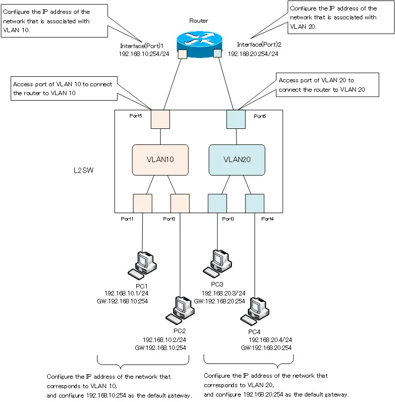
Port 5 of the Layer 2 switch is physically connected to interface (port) 1 of the router. This wiring is for connecting VLAN 10. In the Layer 2 switch, port 5 is configured as the access port for VLAN 10, and the IP address 192.168.10.254/24 in 192.168.10.0/24, which is associated with VLAN 10, is configured in interface 1 of the router. In addition, PC1 and PC2 are connected to VLAN10. These PCs are also configured with IP addresses in 192.168.10.024 that correspond to VLAN 10. In addition, configure the IP address 192.168.10.254 of the VLAN 10 router as the default gateway.
The connection between port 6 of the Layer 2 switch and interface 2 of the router is the physical connection for VLAN 20. Port 6 on the Layer 2 switch is configured as the access port for VLAN 20, and IP address 192.168.20.254/24 in 192.168.20.0/24, which is associated with VLAN 20, is configured on Interface 2 of the router. For PC3 and PC4 in VLAN 20, configure the IP address in 192.168.20.0/24 and the default gateway 192.168.20.254 that are associated with VLAN 20.
As described above, VLANs can be interconnected by physically connecting a router and a Layer 2 switch for each VLAN and then configuring the appropriate settings. If you have many VLANs, you need many connections between the router and the Layer 2 switch. If you add more VLANs later, you will also need to add more cabling.
Trunk link between router and Layer 2 switch (Router-on-a-stick)
It is also possible to connect a router and a Layer 2 switch with only one physical link between them. A network configuration in which routers and Layer 2 switches are connected by a single link to perform inter-VLAN routing is called “Router-on-a-stick”.
A single physical connection between a router and a Layer 2 switch is considered a trunk link. For this purpose, a port on the Layer 2 switch side is configured as a trunk port. Configuring a port as a trunk port means that the port can be divided and treated as a separate port for each VLAN. If the Layer 2 switch has two VLANs, the trunk port will be divided into two.
And in principle, a router connects one network with one interface. Even on the router side, one interface is physically divided into multiple interfaces. However, please note that on the router side, the term “sub-interface” is used instead of “trunk port”. Although the wording is different, a sub-interface of an Ethernet interface is equivalent to a trunk port. A sub-interface allows the physical Ethernet interface of a router to be divided into separate VLANs.
The following figure shows an example of a router interconnecting two VLANs, VLAN10 and VLAN20, of a Layer 2 switch as a trunk link between the router and the Layer 2 switch.
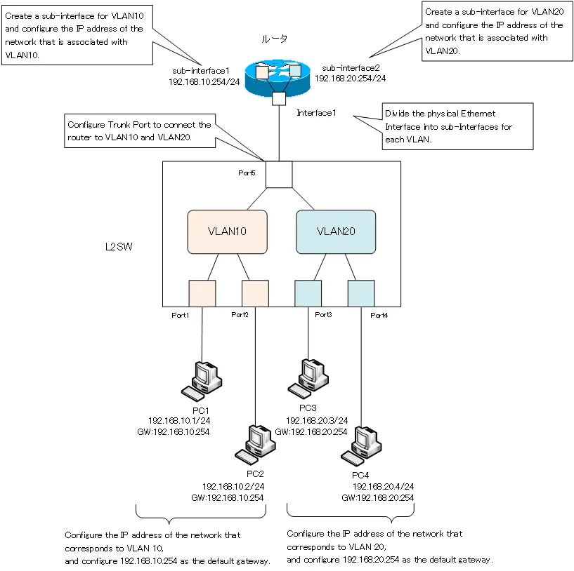
Only port 5 of the Layer 2 switch and interface 1 of the router are connected. By configuring port 5 of the Layer 2 switch as a trunk port, port 5 can be assigned to both VLAN 10 and VLAN 20. This allows port 5 to be divided into two separate VLANs, VLAN 10 and VLAN 20.
Since the ports are divided into VLANs on the Layer 2 switch, interface 1 on the router on the other side of the switch must also be divided into VLANs. The router is divided into two subinterfaces: subinterface 1 for VLAN 10 and subinterface 2 for VLAN 20. subinterface 1 for VLAN 10 is configured to handle the VLAN tag for VLAN 10. And sub-interface 1 is connected to VLAN 10 by configuring the IP address 192.168.10.254/24 in 192.168.10.0/24, which is associated with VLAN 10. Similarly, configure sub-interface 2 for VLAN 20 to handle the VLAN tag for VLAN 20, and configure the IP address 192.168.20.254/24 in 192.168.20.0/24 that corresponds to VLAN 20.
The configuration of PC1 to PC4 is exactly the same as for the connection using access links for each VLAN.
Using trunk links, the connection between the router and the Layer 2 switch can be consolidated into a single link. Even if a VLAN is added later, you can simply create a sub-interface for the added VLAN on the router side. However, if a lot of communication takes place between VLANs, the link between the router and the Layer 2 switch is likely to become a bottleneck.
For specific configuration commands for inter-VLAN routing on Cisco routers, please refer to the following article.
VLAN(Virtual LAN)
- The need to divide the network
- Details of dividing the network
- VLAN Overview
- VLAN behavior
- Access port : Port assigned to only one VLAN
- Trunk port : Port assigned to multiple VLANs
- Summary of Trunk Protocols – IEEE802.1Q and ISL
- Native VLAN
- Specific example of native VLAN mismatch
- Cisco DTP
- Cisco Configuring and Verifying VLAN
- Cisco VLAN Detailed Configuration Example
- Notes on deleting VLANs
- Voice VLAN – VLAN for connecting IP phones
- VTP :Synchronize VLAN configuration
- VTP pruning – Stopping unnecessary flooding of trunk links
- Configuring and Verifying Cisco VTP
- Inter VLAN routing overview
- Inter-VLAN routing by router
- Inter-VLAN routing by Layer 3 switch
- Configuring and Verifying Inter-VLAN Routing by Cisco Router
- Cisco Configuring Inter-VLAN routing by Layer3 switch : SVI/routed port
- Cisco Layer3 Switch Basic Configuration Example
- Summary of Layer 3 Switch Port Concepts – Access Port/Trunk Port/SVI/Routed Port
- LAN Design pattern : 2-tier and 3-tier