
Table of Contents
IP Telephony Overview
IP telephony, which enables voice calls over TCP/IP networks, is increasingly being deployed in corporate internal networks.
IP telephony replaces existing telephones with IP phones, which can convert and transfer voice into IP packets on the phone itself and are connected to a LAN.
Then, connect an IP-PBX to the LAN to control the IP Phone calls. IP-PBX can be a dedicated device or a server with dedicated software installed; IP-PBX is also called a “call control server”. Cisco offers Cisco Unified Communication Manager as an IP-PBX.
Connecting IP Phone
The IP Phone connects directly to the switch. This means that more ports are needed on the switch to connect the IP phones. Two ports per user, one for the host and one for the IP phone, is twice as many as a simple calculation would require.
To reduce the port consumption of the switch, there is an IP Phone with two Ethernet ports; the IP Phone functions as a simple switch, and the host can connect to the switch via the IP Phone to access the corporate LAN, as shown in the following figure.

Based on the physical connection configuration above, divide the logical configuration into two parts: the data VLAN to which the host belongs, and the Voice VLAN to which the IP Phone belongs.
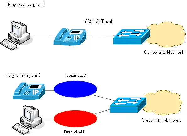
By dividing into Data VLAN and Voice VLAN, it is possible to logically separate IP Phone packets from host packets. It is recommended that IP Phone voice packets should be forwarded with a one-way delay of 150ms or less. To achieve this, QoS is performed. With Voice VLAN, the IP address of the IP Phone voice packets will be that of the Voice VLAN network. This makes it easier to identify the voice packets and to configure QoS.
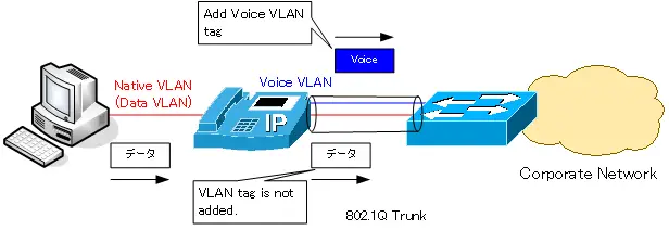
The VLAN for data is usually the native VLAN for IEEE802.1Q trunks. In other words, data sent from the host is forwarded from the IP phone to the switch without any VLAN tag, and the IP phone sends voice packets to the switch with the Voice VLAN tag. In addition to the priority control based on IP address, it is also possible to set the Priority of the Voice VLAN VLAN tag to a specific value to give priority to the IP Phone packets.
Configure the switch to connect the IP Phone (Voice VLAN).
This section explains how to configure the switch to connect an IP Phone. Cisco’s Voice VLAN configuration is easier to understand if you think of it as “an access port that can be assigned to two VLANs, a data VLAN and a Voice VLAN”. Originally, an access port is a port that is assigned to only one VLAN, but the Voice VLAN configuration allows for the assignment of one additional VLAN.
Configure the following commands in the interface configuration mode for the port to which the IP Phone and host are connected.
Switch(config-if)#switchport mode access
Switch(config-if)#switchport access vlan <vlan-id>
<vlan-id> : Data VLAN ID
Data VLAN assignment is the configuration of VLAN membership as an access port, switchport access vlan command. Ethernet frames in the data VLAN are treated as native VLANs without VLAN tagging.
Switch(config-if)#switchport voice vlan <vlan-id>
<vlan-id> : Voice VLAN ID
Then voice VLAN assignment is specified by the switchport voice vlan command. A VLAN tag will be added to the Ethernet frame of the Voice VLAN to which the IP Phone will be connected.
Switch(config-if)#spanning-tree portfast
Also, enable PortFast with the spanning-tree portfast command so that the port is immediately available when the IP Phone is connected to the switch.
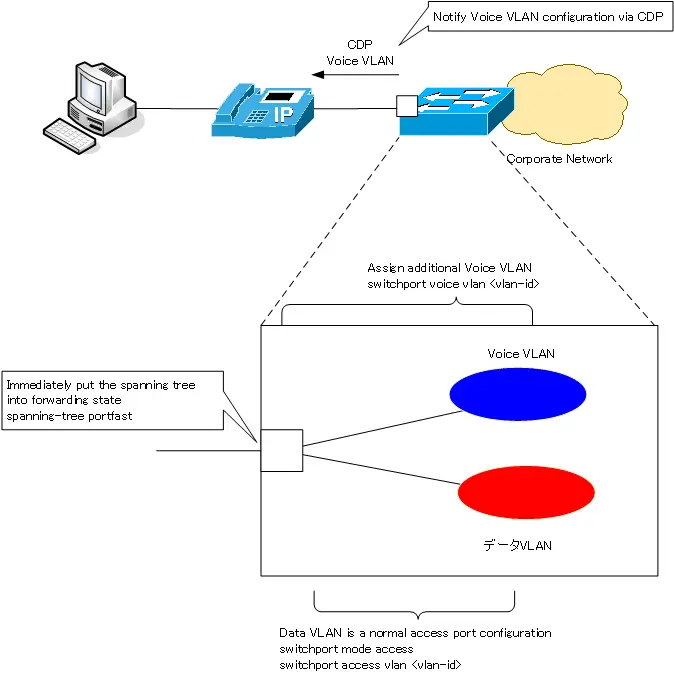
In order to forward Ethernet frames of data VLAN and Voice VLAN from IP Phone to the switch, the IP Phone also needs the Voice VLAN information.The Voice VLAN information configured on the switch side will be notified to the IP Phone via CDP.
Voice VLAN Configuration Example
Consider the following example of configuring the Voice VLAN of SW1 in the figure below.
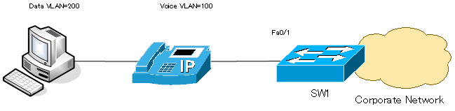
SW1
interface fastethernet0/1
 switchport mode access
 switchport access vlan 200
 switchport voice vlan 100
 spanning-tree portfast
To verify the VLAN number of Voice VLAN, use the show interface switchport command. The show command example is as follows
SW1#show interfaces fastethernet0/1 switchport
Name: Fa0/1
Switchport: Enabled
Administrative Mode: static access
Operational Mode: static access
Administrative Trunking Encapsulation: negotiate
Operational Trunking Encapsulation: native
Negotiation of Trunking: Off
Access Mode VLAN: 200 (VLAN0200)
Trunking Native Mode VLAN: 1 (default)
Voice VLAN: 100 (VLAN0100)
- omitted -
Also, if you verify the show vlan brief, you will see Fa0/1 as an access port for two VLANs: data VLAN and voice VLAN.
SW1#show vlan brief

VLAN Name                             Status    Ports
---- -------------------------------- --------- -------------------------------
1    default                          active    Fa0/2, Fa0/3, Fa0/4, Fa0/5
                                                Fa0/6, Fa0/7, Fa0/8, Fa0/9
                                                Fa0/10, Fa0/11, Fa0/12, Fa0/13
                                                Fa0/14, Fa0/15, Fa0/16, Fa0/17
                                                Fa0/18, Fa0/19, Fa0/21, Fa0/22
                                                Fa0/23, Fa0/24, Gi0/1, Gi0/2
100  VLAN0100                         active    Fa0/1
200  VLAN0200                         active    Fa0/1
1002 fddi-default                     act/unsup
1003 token-ring-default               act/unsup
1004 fddinet-default                  act/unsup
1005 trnet-default                    act/unsup
Fa0/1 is a trunk port in operation because it is able to forward Ethernet frames of two VLANs, VLAN100 and VLAN200. Normally, trunk ports are not displayed in the show vlan brief command. However, Cisco’s Voice VLAN is a configuration that adds one additional VLAN to be assigned as an access port. Therefore, Fa0/1 will be displayed by the show vlan brief command.
VLAN(Virtual LAN)
- The need to divide the network
- Details of dividing the network
- VLAN Overview
- VLAN behavior
- Access port : Port assigned to only one VLAN
- Trunk port : Port assigned to multiple VLANs
- Summary of Trunk Protocols – IEEE802.1Q and ISL
- Native VLAN
- Specific example of native VLAN mismatch
- Cisco DTP
- Cisco Configuring and Verifying VLAN
- Cisco VLAN Detailed Configuration Example
- Notes on deleting VLANs
- Voice VLAN – VLAN for connecting IP phones
- VTP :Synchronize VLAN configuration
- VTP pruning – Stopping unnecessary flooding of trunk links
- Configuring and Verifying Cisco VTP
- Inter VLAN routing overview
- Inter-VLAN routing by router
- Inter-VLAN routing by Layer 3 switch
- Configuring and Verifying Inter-VLAN Routing by Cisco Router
- Cisco Configuring Inter-VLAN routing by Layer3 switch : SVI/routed port
- Cisco Layer3 Switch Basic Configuration Example
- Summary of Layer 3 Switch Port Concepts – Access Port/Trunk Port/SVI/Routed Port
- LAN Design pattern : 2-tier and 3-tier