Table of Contents
Overview
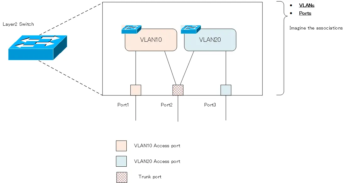
This section details the configuration and verification commands for VLANs on Cisco IOS.When creating a VLAN, the key is to imagine the association between the VLAN and the port inside the Layer 2 switch.
VLAN Configuration Process
First, let’s review the overall configuration flow. The following is the configuration flow for VLANs on Catalyst switches.
Create VLANs
By default, VLAN1 is present. Create additional VLANs as needed. A VLAN is a virtual Layer 2 switch that is created by configuration inside the Layer 2 switch.
Configure Switchport
Assign ports to the created VLANs, i.e., virtual Layer 2 switches. An access port is a port that is assigned to only one VLAN. Trunk ports are ports that are assigned to multiple VLANs.
By default, VLAN1 is present on the switch. All ports are in a specific DTP mode, depending on the model of the Catalyst; on the Catalyst 3560/3750, the mode is Dynamic auto. Therefore, when no Catalyst switch is connected, all ports will act as access ports. When operating as an access port, the VLAN membership is VLAN1.
From here, you can create a new VLAN or change the DTP mode as needed to make it work as an access port/trunk port. For access ports, determine the VLAN membership, and for trunk ports, specify the trunk encapsulation protocol, etc.
By default, VLANs 1002 through 1005 are also present. Since these are not VLANs for Ethernet, you usually do not need to consider them.
Related articl
Please refer to the following articles for more information about access ports and trunk ports.
Create VLANs
To create new VLANs on the switch, use the following command in global configuration mode.
Create VLANs
(config)#vlan <vlan-id>
(config-vlan)#name <vlan-name>
<vlan-id> : VLAN ID
<vlan-name> :VLAN Name
The VLAN name configuration is optional. If omitted, the default name is “VLANxxxx” (xxxx: 4-digit VLAN number string).There are two types of VLAN ID: standard VLAN ID and extended VLAN ID.
- standard VLAN ID
- 1 to 1005
- 1002 to 1005 are reserved for Token Ring or FDDI
- extended VLAN ID
- 1006~4094
- To create a VLAN with an extended VLAN ID, you need to be in VTP transparent mode.
- VLANs with extended VLAN ID will not be advertised in VTP and will not be synchronized with other switches.
- VLANs with extended VLAN ID are not stored in the VLAN database.
Multiple VLANs can also be created in a batch. Multiple VLANs with consecutive VLAN numbers can be created in a batch by using “-” (hyphen). Multiple VLANs with non-consecutive VLAN numbers separated by “,” (comma) can be created in a batch. For example, to create VLAN 5 and VLAN 10 from VLAN 2 in one batch, enter the following command.
Example of batch creation of multiple VLANs
vlan 2-5,10
Deleting VLANs
Since VLANs are created by configuration, they can of course be deleted; to delete a VLAN, simply follow Cisco’s command delete format and enter the command with a “no”.
Deleting VLANs
(config)#no vlan <vlan-id>
<vlan-id> : 削除したいVLAN番号
You can also delete multiple VLANs at once by using “- (hyphen)” or “, (comma)”. Note that deleting a VLAN will disable the access port for that VLAN.
Related article
The following article explains in detail what to do when deleting a VLAN.
Switchport Configuration
DTP mode can be configured in interface configuration mode with the following command. This means assigning ports to virtual Layer 2 switch.
DTP mode configuration
(config)#interface <interface-name>
(config-if)#switchport mode {dynamic {auto | desirable} | trunk |access}
<interface-name> : interface name
Configure the DTP mode appropriately to operate as an access port or trunk port. Most configurations will be static access ports/trunk ports rather than setting the DTP mode to dynamic auto/desirable and dynamically determining the access port/trunk port.
Related article
Access port
To make a port on the switch a static access port and determine its VLAN membership, configure it in interface configuration mode as follows
Access port configuration
(config)#interface <interface-name>
(config-if)#switchport mode access
(config-if)#switchport access vlan <vlan-id>
<interface-name> : interface name
<vlan-id> : VLAN ID to be assigned
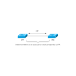
If you want to use a static access port, it is better to disable DTP.
Disable DTP
(config-if)#switchport nonegotiate
Trunk port
To configure a port on the switch as a static trunk port, configure it as follows.
Trunk port configuration
(config)#interface <interface-name>
(config-if)#switchport trunk encapsulation {dot1q | isl}
(config-if)#switchport mode trunk
<interface-name> : interface name
The switchport trunk encapsulation command is required only when both 1Q and ISL trunk protocols are supported. Also, it is still better to disable DTP when static trunk ports are used.
The trunk port is connected to all VLANs inside the switch by default. If necessary, you can limit the VLANs that are connected to the trunk port. The command to do so is as follows
allowed vlan
(config-if)#switchport trunk allowed vlan [add | all | except | remove] <vlan-list>
<vlan-list> : List of VLAN IDs allowed on the trunk
Also, for IEEE802.1Q trunks, specify the native VLAN. To specify the native VLAN, configure it in interface configuration mode as follows
Native VLAN
(config-if)#switchport trunk native vlan <vlan-id>
<vlan-id> : VLAN ID of the native VLAN
In addition, the following command adds a VLAN tag to the Ethernet frame of the native VLAN.
Native VLAN tagging
(config)#vlan dot1q tag native
Related article
Verify the VLAN and switchport configuration.
The following table lists the commands for verifying the VLAN and access port and trunk port configurations.
| show commands | Display Contents |
|---|---|
| #show vlan [brief] | Displays the VLANs present on the switch and the access ports assigned to each VLAN. |
| #show interface trunk | Displays summary information for trunk ports on the switch. |
| #show interface <interface-name> switchport | Displays detailed switch port (access port/trunk port) status. |
Example of VLAN and switchport configuration
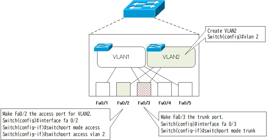
The following figure models the internal structure of a Catalyst switch in its default state, assuming a Catalyst 2970 series switch.
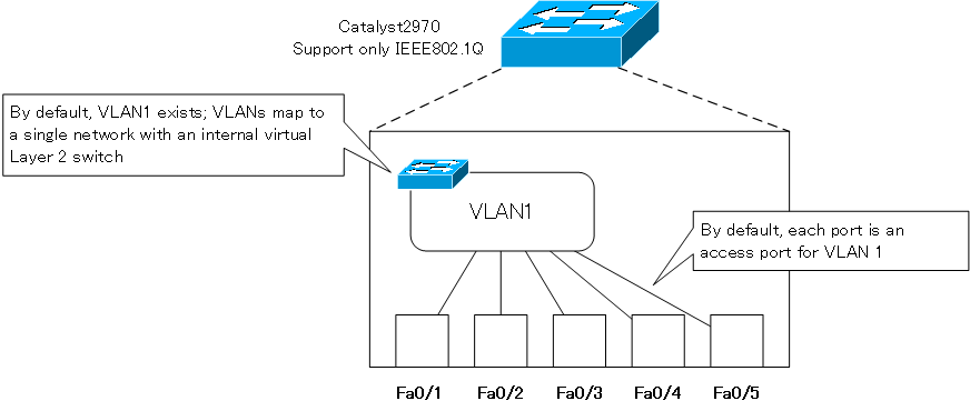
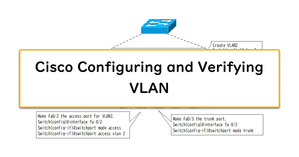
Configure the following on the Catalyst switch in the default state.
- Create VLAN2
- Make Fa0/2 the access port for VLAN2
- Make Fa0/3 a trunk port for IEEE802.11Q
Create VLAN2
First, create VLAN2.
Create VLAN2
vlan 2
This configuration creates a virtual VLAN 2 switch inside the switch. You can name the VLAN for clarity if you want.
Make Fa0/2 the access port for VLAN2
Then, assign ports to the virtual switch of VLAN2 that you created. To make Fa0/2 the access port for VLAN2, use the following command.
Fa0/2 VLAN2 access port configuration
interface FastEthernet0/2
 switchport mode access
 switchport access vlan 2
This configuration will connect Fa0/2 and VLAN2.
Make Fa0/3 a trunk port for IEEE802.11Q
To make Fa0/3 a trunk port for IEEE802.1Q, configure as follows.
Fa0/3 Trunk port configuration
interface FastEthernet0/3
 switchport mode trunk
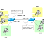
Then Fa0/3 will be connected to both VLAN1 and VLAN2, and the frame can be forwarded with the identification information of each VLAN added.The Catalyst 2970 series supports only IEEE802.1Q. switchport trunk The encapsulation command is not required.
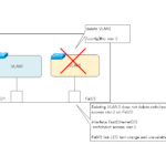
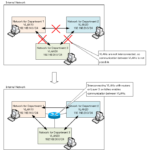
With the configuration so far, the internal connections of the Catalyst switch are shown in the following figure.
Looking at the internal connections in this way, it is easy to see why Fa0/1, the access port for VLAN1, and Fa0/2, the access port for VLAN2, cannot communicate directly with each other. This is because although they are ports on the same switch, Fa0/1 and Fa0/2 are not connected inside the switch.
In order to allow ports of different VLANs to communicate with each other, it is necessary to use a Layer 3 switch or router to perform inter-VLAN routing.
Related article
See also the following article regarding inter-VLAN routing.
Sample output of verification command
Let’s look at the actual verification command for the above configuration.
show vlan brief
First, use the show vlan brief command to verify the VLANs and access ports inside the switch.
show vlan brief
Switch#show vlan brief

VLAN Name                             Status    Ports
---- -------------------------------- --------- -------------------------------
1    default                          active    Fa0/1, Fa0/4, Fa0/5, Fa0/6
                                                Fa0/7, Fa0/8, Fa0/9, Fa0/10
                                                Fa0/11, Fa0/12, Fa0/13, Fa0/14
                                                Fa0/15, Fa0/16, Fa0/17, Fa0/18
                                                Fa0/19, Fa0/20, Fa0/21, Fa0/22
                                                Fa0/23, Fa0/24, Gi0/1, Gi0/2
2    VLAN0002                         active    Fa0/2
1002 fddi-default                     act/unsup
1003 token-ring-default               act/unsup
1004 fddinet-default                  act/unsup
1005 trnet-default                    act/unsup
You can see that VLAN2 exists and Fa0/2 is its access port.
Note that Fa0/3 is not included as an access port in the default VLAN1; Fa0/3 will not appear in the show vlan brief because it is configured as a trunk port.
show interface trunk
To verify the trunk ports, use the show interface trunk command. With this command, you can verify the summary information of all trunk ports on the switch. The sample output in the configuration example is shown below.
show interface trunk
Switch#show interfaces trunk

Port        Mode         Encapsulation  Status        Native vlan
Fa0/3       on           802.1q         trunking      1

Port      Vlans allowed on trunk
Fa0/3       1-4094

Port        Vlans allowed and active in management domain
Fa0/3       1-2

Port        Vlans in spanning tree forwarding state and not pruned
Fa0/3       1-2
You can see the trunk protocol of Fa0/3 configured on the trunk port and the VLAN information to be forwarded on the trunk port. Each item in the command output represents the following information.
- Vlans allowed on trunk
The contents of the switchport trunk allowed vlan command will be reflected. The default is all VLANs from 1-4094. - Vlans allowed and active in management domain
Of the allowed VLANs, the active VLANs that are actually connected to the trunk port will be displayed. - Vlans in spanning tree forwarding state and not pruned
The VLAN IDs that are actually forwarded from the trunk port, based on the spanning tree calculation and VTP pruning, is displayed. To verify the VLANs that will be forwarded from the trunk port, look at this part
show interface switchport
Also, to verify the detailed information as a switch port, use the show interface switchport command. show interface switchport command for Fa0/2 and Fa0/3 is as follows
show interface switchport
Switch#show interfaces fa 0/2 switchport
Name: Fa0/2
Switchport: Enabled
Administrative Mode: static access
Operational Mode: static access
Administrative Trunking Encapsulation: dot1q
Operational Trunking Encapsulation: native
Negotiation of Trunking: Off
Access Mode VLAN: 2 (VLAN0002)
Trunking Native Mode VLAN: 1 (default)
Voice VLAN: none
-- omitted --

Switch#show interfaces fa 0/3 switchport
Name: Fa0/3
Switchport: Enabled
Administrative Mode: trunk
Operational Mode: trunk
Administrative Trunking Encapsulation: dot1q
Operational Trunking Encapsulation: dot1q
Negotiation of Trunking: On
Access Mode VLAN: 1 (default)
Trunking Native Mode VLAN: 1 (default)
Voice VLAN: none
-- omitted --
Trunking VLANs Enabled: ALL
-- omitted --
In addition to the information as an access port or trunk port, you can verify various Layer 2 level functions, which are displayed differently depending on the Catalyst switch model and IOS version, but the main items are explained below.
- Administrative Mode
Indicates the configured DTP mode. - Operational Mode
Indicates whether the port is actually operating as a trunk port or as an access port. - Administrative Trunking Encapsulation
Indicates the trunk protocol configuration. - Operational Trunking Encapsulation
Indicates the trunk protocol that is actually being used. - Negotiation of Trunking
Indicates whether negotiation by DTP is enabled. - Access Mode VLAN
Indicates the VLAN ID for VLAN membership when that port becomes an access port. - Trunking Native Mode VLAN
Indicates the VLAN number of the native VLAN for 1Q trunks. The native VLAN is meaningful only for IEEE802.1Q trunks. - Voice VLAN
Indicates the VLAN ID of the Voice VLAN to which the IP Phone is connected. - Trunking VLANs Enabled
Indicates the VLAN IDs allowed by the switchport trunk allowed vlan command. The default is 1-4904 (all).
まとめ
Points
- When configuring VLANs, it is important to imagine the association between VLANs and ports inside the Layer 2 switch.
- Flow of VLAN configuration
- Creating VLANs
- Assigning ports to the created VLANs
VLAN(Virtual LAN)
- The need to divide the network
- Details of dividing the network
- VLAN Overview
- VLAN behavior
- Access port : Port assigned to only one VLAN
- Trunk port : Port assigned to multiple VLANs
- Summary of Trunk Protocols – IEEE802.1Q and ISL
- Native VLAN
- Specific example of native VLAN mismatch
- Cisco DTP
- Cisco Configuring and Verifying VLAN
- Cisco VLAN Detailed Configuration Example
- Notes on deleting VLANs
- Voice VLAN – VLAN for connecting IP phones
- VTP :Synchronize VLAN configuration
- VTP pruning – Stopping unnecessary flooding of trunk links
- Configuring and Verifying Cisco VTP
- Inter VLAN routing overview
- Inter-VLAN routing by router
- Inter-VLAN routing by Layer 3 switch
- Configuring and Verifying Inter-VLAN Routing by Cisco Router
- Cisco Configuring Inter-VLAN routing by Layer3 switch : SVI/routed port
- Cisco Layer3 Switch Basic Configuration Example
- Summary of Layer 3 Switch Port Concepts – Access Port/Trunk Port/SVI/Routed Port
- LAN Design pattern : 2-tier and 3-tier