Table of Contents
The main interfaces of Cisco devices
It is a network infrastructure that allows physical signals to be exchanged by connecting transmission media to interfaces such as Cisco devices, PCs, and servers to form a link. While “interface” means “boundary,” a network interface is the boundary between “0” and “1” digital data and physical signals, such as electrical signals.
Cisco devices can be equipped with many different types of interfaces, the main ones being the following
- Ethernet interface
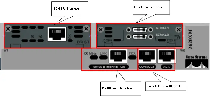
It is an interface for building an Ethernet LAN. The most common connector for Ethernet interfaces is the RJ45 connector and the cable is a UTP cable. In addition to LANs, Ethernet is now widely used as an interface to connect to WAN services as well. - Serial interface
This interface is used to connect the router to a leased line or other WAN service. There are many standards for serial interfaces, each with different connectors and cables. A commonly used serial interface is a smart serial connector with a smart serial cable connected to a smart serial connector. - ISDN interface
An interface for connecting routers to the ISDN network. New ISDN networks are no longer used, but some previously operational networks still make use of the ISDN interface. - Console port,AUX port
These are interfaces used to configure Cisco devices rather than interfaces for connecting to the network. In terms of notation, we generally use “port” rather than “interface”.
Depending on how many interfaces Cisco devices can be added or changed at a later time, the following are available
- Fixed devices
- Modular devices
Fixed devices basically cannot be added or changed at a later time. Modular devices allow you to add or change the type and number of interfaces by adding or replacing modules at a later date. Modular devices are larger devices for relatively large scale applications, also known as chassis devices.
Interface name
Routers and switches come with multiple interfaces of various types. When configuring an interface or creating a network diagram, you need to be able to identify the interface by its name rather than a simple number. The format is as follows.
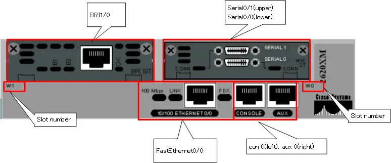
<interface-type> <slot> / <port>
For example, the interface name is determined as “GigabitEthernet0/1”. You can use the abbreviated form “gi0/1” or “g0/1”.
The following table summarizes the main interface types
| Interface | <interface-type> |
| Ethernet | Ethernet |
| FastEthernet | FastEthernet |
| GigabitEthernet | GigabitEthernet |
| 10GigabitEthernet | TenGigabitEthernet |
| Serial | Serial |
| ISDN BRI | BRI |
For fixed devices, <slot> is basically a fixed zero. Some fixed-type devices have a slot for a network module, and you can specify the slot number for that slot. In the case of a modular device interface, it specifies the slot number in which the module is inserted. <port> is simply the port number. Note that router port numbers start at “0”, but Catalyst switches have their port numbers starting at “1”.
Note that the interface name of the console port is “con 0” and the interface name of the auxiliary port is “aux 0”. The console port and auxiliary port are not used to send and receive data. They are used to exchange configuration and confirmation commands and command execution results. When configuring a console or auxiliary port, enter “line con 0” or “line aux 0” instead of the interface configuration mode to go to line configuration mode and execute commands.
Virtual Interface
In addition to a physical interface to connect a transmission medium (cable) to a Cisco device to convert a “0” or “1” digital signal into a physical signal and send it out, a virtual interface can also be added to the device. A virtual interface is an interface that is created by configuration inside a device for some special purpose, rather than physically connecting the transmission medium. A virtual interface is also called a logical interface.
There are various types of virtual interfaces, and the following are the main virtual interfaces
- loopback interface
- sub interface
- tunnel interface
- Port-Channel interface
- VTY
Loopback interface
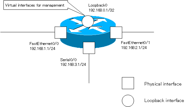
The loopback interface is an interface used for device management purposes. Routers, in particular, have multiple physical interfaces, and IP addresses are set for each interface. You have to think about which interface’s IP address to use when you remotely access the router. If the interface is down, the IP address of that interface will not be available.
A loopback interface is a virtual interface that is created internally and can be used as long as it is not explicitly disabled or all physical interfaces are down. If you set an IP address for the loopback interface and ensure connectivity to that IP address, you can always use a fixed IP address when accessing the router remotely.
In addition, the IP address of the loopback interface can be used as the router ID to identify each router in routing protocols such as OSPF and BGP.
The <interface-type> of the loopback interface is “loopback”. To create a loopback interface, enter a command to go from global configuration mode to interface configuration mode for the loopback interface.
(config)#interface loopback <number>
(config-if)#
<number> : Loopback interface number 0~2147473647
The loopback interface can be configured with an IP address in the same way as a normal physical interface.
Sub Interface
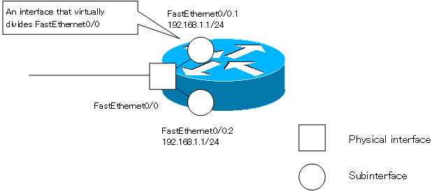
A subinterface is a virtual division of a physical interface. the CCNA exam requires knowledge of splitting the Ethernet interface with a subinterface.
A subinterface is identified “<interface-type>.<subinterface-number>”.When you create a FastEthernet0/0 subinterface or go to interface configuration mode for a subinterface, enter the following commands in global configuration mode.
(config)#interface FastEthernet0/0.<subinterface-number>
(config-subif)#
<subinterface-number> : Subinterface number 0~4294967295
The IP address can be configured for the subinterfaces. However, you must also configure the correspondence between the VLAN and the subinterface.
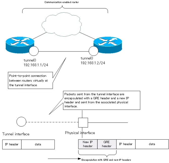
Tunnel interface
The tunnel interface allows routers capable of communicating via IP to be treated as if they were connected virtually point-to-point (one-to-one). The tunnel interface is often used when building a VPN (Virtual Private Network).
The <interface-tyep> of the tunnel interface is “tunnel”. The IP packets handled by the tunnel interface are encapsulated with a GRE (Generic Routing Encapsulation) header and a new IP header. In the configuration of the tunnel interface, specify the destination and source IP address of the new IP header.
(config)#interface tunnel <number>
(config-if)#tunnel source <interface-name> | <tunnel-source-ip-address>
(config-if)#tunnel destination <tunnel-destination-ip-address>
<number> : Tunnel interface number 0~2147473647
<interface-name> : Interface name to be used as the source IP address for the new IP header
<tunnel-source-ip-address> : Source IP address of the new IP header
<tunnel-destination-ip-address> : Destination IP address of the new IP header
Just like a normal interface, the tunnel interface can be configured with an IP address.
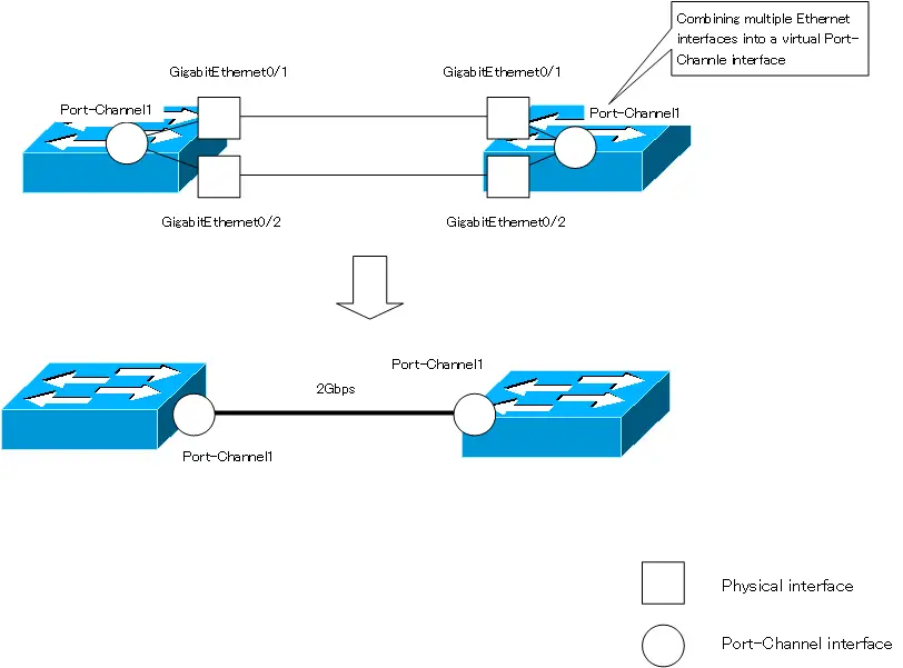
Port-Channel interface
The Port-Channel interface is an interface that virtually combines multiple Ethernet interfaces into one interface on a Layer 2/Layer 3 switch. The function of combining multiple Ethernet interfaces is called “EtherChannel”, and when EtherChannel is enabled, a Port-Channel interface will be created.
By using EtherChannel, you can treat two 1000BASE-T Ethernet interfaces as if they were virtually connected by a single 2Gbps link. In other words, EtherChannel can speed up communication. And as long as the links are not all down, the communication can continue.
The <interface-type> of the Port-Channel interface is “Port-Channel.” To create a Port-Channel interface or to enter the interface configuration mode for a Port-Channel interface, use the following command.
(config)#interface Port-channel <number>
(config-if)#
<number> : Port-Channel interface number 1~64
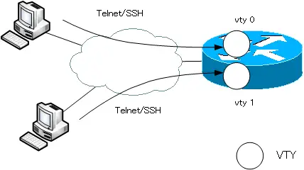
VTY
VTY is a virtual interface that accepts CLI-based remote accesses such as Telnet/SSH, etc. Unlike the virtual interfaces presented here, VTY is configured in line configuration mode.
(config)#line vty <first-line-number> <last-line-number>
(config-line)#
<first-line-number> : start of line number
<last-line-number> : end of line number
The maximum number of line numbers that can be specified depends on the IOS version. The default setting is “line vty 0 4”, which uses five line numbers from 0 to 4.
Point-to-point and multi-access interfaces
The following classifications of interfaces are also available
- Point-to-point interfaces
- Multi-access interfaces
This classification is based on the number of other interfaces that connect on the same network.
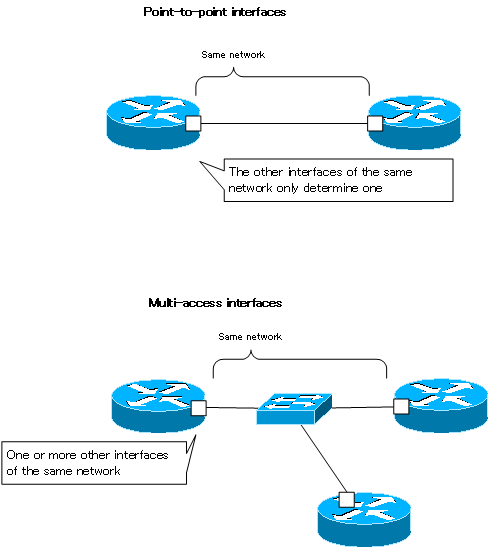
Point-to-point interfaces
A point-to-point interface determines just one other interface that connects on the same network. It is literally a “one-to-one” interface that is connected in a “one-to-one” fashion; a serial interface with a PPP or HDLC encapsulation setup is a typical point-to-point interface.
In a point-to-point interface, if data is converted into a physical signal and sent out, it will always be transmitted to a specific interface. There is no particular need for an address to identify the interface on the other side.
Multi-access interfaces
A multi-access interface, on the other hand, has one or more other interfaces that connect on the same network. A typical multi-access interface is an Ethernet interface. Multi-access interfaces are sometimes referred to as multipoint interfaces.
In the case of multi-access interfaces, simply converting data into physical signals and sending them out does not necessarily mean that they will be transmitted to the appropriate interface. The appropriate interface is identified by addresses, such as MAC addresses, at the data link layer level.
Cisco Basic
- Preparing for Cisco devices configuration
- Configuration files for Cisco devices
- The configuration steps for Cisco devices
- Basic knowledge of the Cisco CLI: Command types and modes
- Cisco device’s interface
- CLI help and completion
- The main error messages in CLI
- Cisco Deleting a configuration command
- default interface command -Initialize the interface settings-
- Entering commands in batches
- do command – Execute EXEC command from configuration mode –
- interface range command -Batch configuration of multiple interfaces-
- Filtering the display of the show command – displaying only the information you want to see –
- Cisco IOS Name Resolution Configuration
- terminal length command : configuration of the number of lines displayed in the command output
- debug command to verify real-time operation
- Automatically enter privileged EXEC mode upon CLI login
- Configure System Clock
- Saving and managing configuration files
- Version Management of Configuration Files ~archive command
- IOS File System Operations
- Managing Cisco Catalyst Switches :What it means to set an IP address on a switch.
- Remote management by VTY access (Telnet/SSH)
- terminal monitor command to display the log of Telnet/SSH login destination
- Multi-step Telnet Session Suspensions
- Set the minimum number of characters in the password [Cisco]
- Restrict login attempts : login block-for command
- Cisco Initial Configuration Example
- CDP – What are the connected devices? –
- Password recovery for Cisco routers
- Password Recovery for Catalyst Switches
