Table of Contents
Initial Configuration of Cisco Routers and Catalyst Switches
We will consider the initial settings of the Cisco router and Catalyst switch in a simple network environment. This time, the items to be set up in the initial configuration are as follows.
- hostname
- login password
- banner message
- IP address
Once you’ve configured it, you should also be aware of the fact that you need to make sure that the configuration is correct.
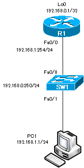
Network diagram
The main commands
The following table summarizes the main configuration and verification commands for initial setup.
| Configuration commands | Summary |
| (config)#hostname | Set the hostname. |
| (conig)#enable secret (config)#enable password | Set the password for entering privileged EXEC mode. |
| (config)#service password-encryption | Encrypt the password display. |
| (config)#banner motd | Set the message to be displayed when you log in. |
| (config)#username password | Set a username and password. |
| (config-line)#login [local] (config-line)#password | Set the password for the console/AUX/VTY. |
| (config-line)#exec-timeout | Specify a timeout period for console and VTY access. |
| (config)#interface loopback | Create a loopback interface. |
| (config-if)#ip address | Set the IP address for the interface. |
| (config-if)#no shutdown | Activate a interface |
| Verification commands | Summary |
| #show running-config | Display contents of running-config |
| #show startup-config | Display contents of startup-config |
| #show interface | Focuses on the details of the Layer 1/Layer 2 state of the interface. |
| #show ip interface [brief] | It focuses on the details of the Layer 3 state of the interface. |
| #show protocols | Displays the interface status and IP address. |
| #ping | Check the connectivity to the specified IP address or host name. |
| #traceroute | Check the communication route to the specified IP address or host name. |
Configuration and verification
Set the host name
Set the host names for the routers and switches.
| Device | hostname |
| Router | R1 |
| Layer2 switch | SW1 |
To set the hostname, enter the following command in global configuration mode
(config)#hostname <hostname>
<hostname> : hostname
The rules for <hostname> are as follows
- Less than 63 characters
- Available Character Types
- Alphabet
- number
- -(hyphen)
- The first character is an alphabet
The following is how the router is configured.
Router>enable
Router#configure terminal
Enter configuration commands, one per line.  End with CNTL/Z.
Router(config)#hostname R1
R1(config)#
As soon as you enter the command, the hostname is “R1”. Also, “hostname R1” is reflected in running-config.
Password configuration for privileged EXEC mode
Use the “enable” command to set a password for entering privileged EXEC mode. There are two commands for configuring the password
(config)#enable password <password>
(config)#enable secret <password>
<password> : password
Passwords set in the “enable secret” command are encrypted when you view the configuration in “show running-config”. On the other hand, passwords set by the “enable password” command are not encrypted when you view the configuration “in show running-config”.
If you configured both, the password configured by the “enable secret” command will be applied. To reduce the chance of the password being leaked to anyone other than the administrator, configure the password “cisco” using the “enable secret” command.
The configuration in R1 is as follows
R1(config)#enable secret cisco
R1(config)#end
R1#disable
R1>enable
Password:
R1#show running-config
Building configuration...

- omitted -
!
hostname R1
!
- omitted -
!
enable secret 5 $1$2MAq$beW3VsjpYu2oo3GvzG7ry/
!
- omitted -
!
After configuring the password for “cisco” with the “enable secret” command, we are back in user EXEC mode. Then the password is prompted for when you go into privileged EXEC mode with the “enable” command. when you view the configuration in “show running-config”, the password string of “cisco” is shown encrypted.
Configuring the Console/AUX/VTY Password
Configure the password for access by console, AUX, VTY, etc. Configures the password in line configuration mode as follows
(config)#line {console 0|aux 0|vty 0 4}
(config-line)#login [local]
(config-line)#password <password>
<password> : password
If you configure “login local”, you can enable authentication with a local username/password. The commands for setting the local username/password are as follows
(config)#username <username> password <password>
<username> : User name
<password> : password
The table summarizes the console/AUX/VTY passwords to be configured in R1 and SW1.
| コンソール | cisco |
| AUX | cisco |
| VTY | Local username/password |
| Username | Password |
| cisco | cisco |
The configuration in R1 is as follows
R1(config)#line con 0
R1(config-line)#login
% Login disabled on line 0, until 'password' is set
R1(config-line)#password cisco
R1(config-line)#exit
R1(config)#line aux 0
R1(config-line)#login
% Login disabled on line 129, until 'password' is set
R1(config-line)#password cisco
R1(config-line)#exit
R1(config)#line vty 0 4
R1(config-line)#login local
R1(config)#username cisco password cisco
Console/AUX/VTY timeout configuration.
If there is no input for a certain period of time when you are logged into the CLI via console or VTY access, the system times out. To change the timeout time, enter the following command in line configuration mode.
(config)#line {con 0|aux 0|vty 0 4}
(config-line)#exec-timeout <minute> <sec>
<minute> : timeout min
<sec> : timeout sec
The default is five minutes. To disable the timeout, use the command “exec-timeout 0 0” to set the timeout time to zero.
Disable the console timeout time in R1. To do so, the command is as follows.
R1(config)#line con 0
R1(config-line)#exec-timeout 0 0
Encryption of password display
The console/AUX/VTY passwords are not encrypted in the running-config display. encrypting the password display in running-config is the preferred configuration for security purposes. You can encrypt the password display by entering the following command in global configuration mode.
(config)#service password-encryption
In R1, it looks like this
R1(config)#service password-encryption
R1(config)#end
R1#show running-config
Building configuration...
- omitted -
service password-encryption
!
!
username cisco password 7 070C285F4D06
!
- omitted -
!
line con 0
 password 7 094F471A1A0A
 login
line aux 0
 password 7 060506324F41
 login
line vty 0 4
 login local
!
end

R1#
Configuring a Banner Message
You can display a banner message on the console when you log in to the device. Enter the following commands in global configuration mode.
(config)#banner motd <message>
<message> : Messages to be displayed
For security purposes, it is preferable to display a banner message that says, “Only authorized users can log in”. The following banner message should be configured.
************************************************
Only administrator can login this device
************************************************
The configuration in R1 is as follows
R1(config)#banner motd ^
Enter TEXT message.  End with the character '^'.
************************************************
Only administrator can login this device
************************************************
^
R1(config)#
The “^” is set as a delimiter. The message will be displayed in multiple lines within the range enclosed by the “^”.
The banner login message also appears before the user authentication prompt, but if you have configured it with a banner motd, it appears afterwards. The banner exec message is the message that appears when you enter EXEC mode after user authentication.
IP Address Configuration
Configure an IP address for the interface. Configuring an interface with an IP address allows you to connect to an IP network and send and receive IP packets. Note that router interfaces are administratively disabled (administratively down) by default with the “shutdown” command. you must enable the interface with the “no shutdown” command. Also, routers are often creating loopback interfaces for management purposes.
(config)#interface <interface-name>
(config-if)#ip address <address> <subnetmask>
(config-if)#no shutdown
<interface-name> : Interface name
<address> <subnetmask> : ip address subnetmask
| Device | Interface | IP address |
| R1 | FastEthernet0/0 | 192.168.1.254/24 |
| Loopback0 | 192.168.0.1/32 | |
| SW1 | Vlan1 | 192.168.1.250/24 |
The configuration in R1 is as follows
R1(config)#interface loopback 0
*Mar  1 01:48:20.763: %LINEPROTO-5-UPDOWN: Line protocol on Interface Loopback0, changed state to up
R1(config-if)#ip address 192.168.0.1 255.255.255.255
R1(config-if)#exit
R1(config)#interface FastEthernet 0/0
R1(config-if)#ip address 192.168.1.254 255.255.255.0
R1(config-if)#no shutdown
R1(config-if)#
*Mar  1 01:48:49.519: %LINK-3-UPDOWN: Interface FastEthernet0/0, changed state to up
*Mar  1 01:48:50.519: %LINEPROTO-5-UPDOWN: Line protocol on Interface FastEthernet0/0, changed state to up
The configuration for SW1 is as follows.
SW1(config)#interface vlan 1
SW1(config-if)#ip address 192.168.1.250 255.255.255.0
Verify the interface
You can verify the interface status and configured IP address. The show command for checking the interface status and IP address is as follows.
- show ip interface [brief]
- show interface
- show protocols
The show command on R1 is displayed as follows
R1#show ip interface brief
Interface                  IP-Address      OK? Method Status                Protocol
FastEthernet0/0            192.168.1.254   YES manual up                    up
Loopback0                  192.168.0.1     YES manual up                    up
R1#show ip interface
FastEthernet0/0 is up, line protocol is up
  Internet address is 192.168.1.254/24
  Broadcast address is 255.255.255.255
  Address determined by setup command
  MTU is 1500 bytes
~省略~
Loopback0 is up, line protocol is up
  Internet address is 192.168.0.1/32
  Broadcast address is 255.255.255.255
  Address determined by setup command
  MTU is 1514 bytes
R1#show interfaces
FastEthernet0/0 is up, line protocol is up
  Hardware is AmdFE, address is cc0c.6410.0000 (bia cc0c.6410.0000)
  Internet address is 192.168.1.254/24
  MTU 1500 bytes, BW 100000 Kbit/sec, DLY 100 usec,
     reliability 255/255, txload 1/255, rxload 1/255
  Encapsulation ARPA, loopback not set
  Keepalive set (10 sec)
  Full-duplex, 100Mb/s, 100BaseTX/FX
Loopback0 is up, line protocol is up
  Hardware is Loopback
  Internet address is 192.168.0.1/32
  MTU 1514 bytes, BW 8000000 Kbit/sec, DLY 5000 usec,
     reliability 255/255, txload 1/255, rxload 1/255
  Encapsulation LOOPBACK, loopback not set
R1#show protocols
Global values:
  Internet Protocol routing is enabled
FastEthernet0/0 is up, line protocol is up
  Internet address is 192.168.1.254/24
Loopback0 is up, line protocol is up
  Internet address is 192.168.0.1/32
Two interface status are displayed as follows
FastEthernet0/0 is up, line protocol is up
The is “<interface-name> is…” is a state at the physical layer , and the “line protocol is …” is a data link layer state. If they are both up, that’s normal. If they are not both up, then there is a problem and the problem needs to be fixed. The following table summarizes the possible cases of the interface state.
| <interface-name> is | line protocol is | meaning |
| administratively down | down | The interface is shutdown. no shutdown required |
| down | down | Physical layer problems. Check cable connections, etc. |
| up | down | Data link layer problems. Checking the Layer 2 encapsulation protocol, etc. |
| up | up | The physical and data link layers are fine. |
Cisco Basic
- Preparing for Cisco devices configuration
- Configuration files for Cisco devices
- The configuration steps for Cisco devices
- Basic knowledge of the Cisco CLI: Command types and modes
- Cisco device’s interface
- CLI help and completion
- The main error messages in CLI
- Cisco Deleting a configuration command
- default interface command -Initialize the interface settings-
- Entering commands in batches
- do command – Execute EXEC command from configuration mode –
- interface range command -Batch configuration of multiple interfaces-
- Filtering the display of the show command – displaying only the information you want to see –
- Cisco IOS Name Resolution Configuration
- terminal length command : configuration of the number of lines displayed in the command output
- debug command to verify real-time operation
- Automatically enter privileged EXEC mode upon CLI login
- Configure System Clock
- Saving and managing configuration files
- Version Management of Configuration Files ~archive command
- IOS File System Operations
- Managing Cisco Catalyst Switches :What it means to set an IP address on a switch.
- Remote management by VTY access (Telnet/SSH)
- terminal monitor command to display the log of Telnet/SSH login destination
- Multi-step Telnet Session Suspensions
- Set the minimum number of characters in the password [Cisco]
- Restrict login attempts : login block-for command
- Cisco Initial Configuration Example
- CDP – What are the connected devices? –
- Password recovery for Cisco routers
- Password Recovery for Catalyst Switches
