
Table of Contents
What is Layer 3 Switch?
Inter-VLAN routing using routers requires an additional router, which complicates the network configuration. In addition, since communication between VLANs is done via routers, the routers become the bottleneck. In order to achieve more efficient inter-VLAN routing, Layer 3 switches are used. A Layer 3 switch incorporates router functions inside a Layer 2 switch, and interconnects VLANs with a Layer 3 switch alone. The router functions are implemented in hardware and can be processed at high speed. Also, since data transfer is a process within a unit of hardware, it is also fast. A Layer 3 switch allows faster communication between VLANs than a router.
Layer 3 switch data forwarding
First, let’s consider the forwarding of data on a Layer 3 switch. A Layer 3 switch also has the functionality of a Layer 2 switch. If the data is forwarded within the same network (VLAN), it will be forwarded to the appropriate port based on the MAC address, just like a Layer 2 switch. And if the data is being forwarded between networks (VLANs), it will forward the data based on IP addresses. The following figure shows an overview of how data is forwarded by a Layer 3 switch.

In the network configuration shown in the figure, two VLANs, VLAN10 and VLAN20, are created on the Layer 3 switch to divide the network. PC1 and PC2 are assigned to VLAN10, and PC3 is assigned to VLAN20.
Then, VLAN10 and VLAN20 are interconnected by a Layer 3 switch, and for the interconnection of the VLANs, we need to configure the IP address, which is explained later in this section.
Forwarding data between PC1 and PC2 in the same VLAN 10 works the same way as a Layer 2 switch: Ethernet frames are forwarded based on the MAC address.
Also, data forwarding between PC1 and PC3 between VLAN10 and VLAN20 works the same way as a router: IP packets are forwarded based on IP addresses.
IP address configuration for Layer 3 Switch.
To interconnect a network with a router, an IP address is configured on the router’s interface. The same is true for Layer 3 switches. To interconnect networks (VLANs) with a Layer 3 switch, you need to configure an IP address on the Layer 3 switch. How to configure an IP address on a Layer 3 switch is an important point in configuring a Layer 3 switch. It is like having an internal router in the Layer 3 switch and configuring the IP address to the internal router. There are two ways to configure IP addresses for Layer 3 switches.
- Configuring an IP address for virtual interface (VLAN interface) inside a Layer 3 switch
- Configuring an IP address for physical interface of a Layer 3 switch
VLAN interface (SVI)
First, let’s talk about configuring IP addresses for the virtual interfaces inside the Layer 3 switch. As with Layer 2 switches, Layer 3 switches create internal VLANs and assign ports to them. Then, there is an internal router inside the Layer 3 switch, and the VLAN is connected to the internal router. The interface that connects the internal router to the VLAN is the VLAN interface, which is created by configuration. By configuring an IP address within the network address corresponding to the VLAN for the VLAN interface, you are connecting the internal router to the VLAN. The VLAN interface is called SVI (Switched Virtual Interface) by Cisco.
Routed port
Next, let’s talk about IP address configuration for the physical interface of a Layer 3 switch. To configure an IP address for the physical interface of a Layer 3 switch, the interface is directly connected to the internal router. Since the interface is directly connected to the internal router, the IP address can be set to the physical interface in the same way as the router. The interface that is directly connected to the internal router is called a routed port. The following figure shows the IP address configuration of a Layer 3 switch.
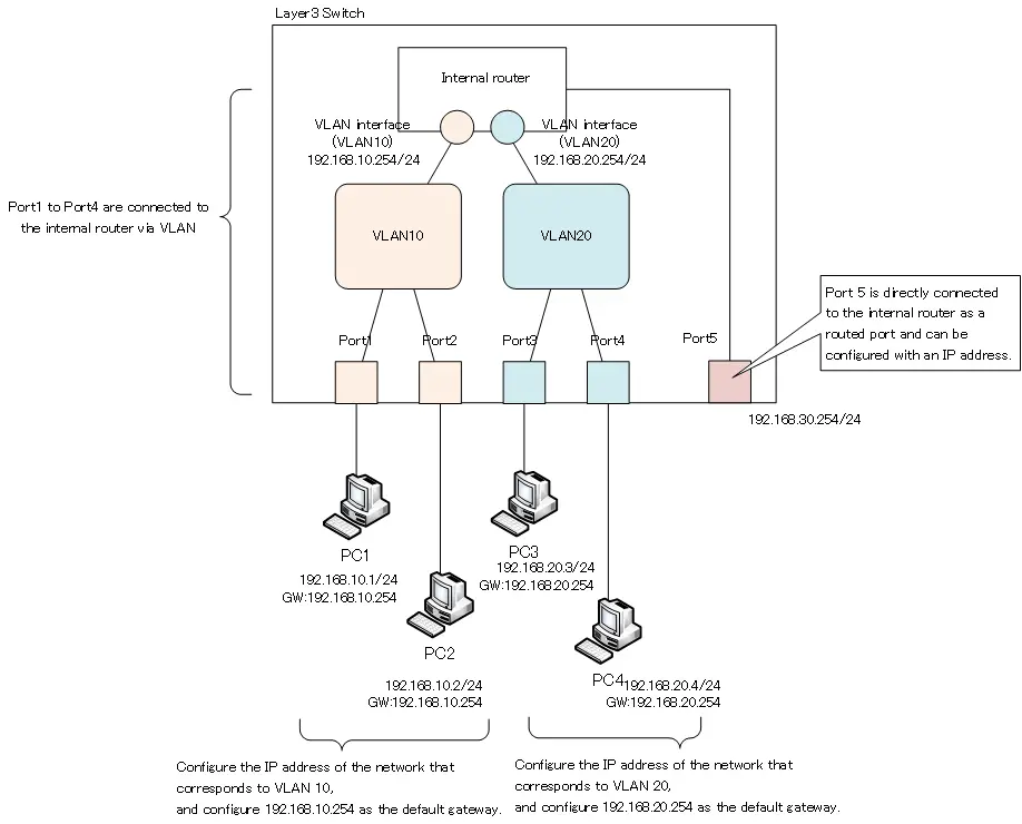
In the figure, VLAN10 and VLAN20 are created on the Layer 3 switch, and ports 1 and 2 are assigned as ports for VLAN10, and ports 3 and 4 are assigned as ports for VLAN20. To communicate between VLAN 10 and VLAN 20, the two VLANs are interconnected through the internal router. To do so, we create a VLAN interface to connect VLAN 10 to the internal router, and configure an IP address of 192.168.10.254/24 corresponding to VLAN 10. Then, VLAN 20 is connected to the internal router with the VLAN 20 interface, and the IP address 192.168.20.254/24 corresponding to VLAN 20 is configured. The IP address of the internal router configured in this way is the IP address of the default gateway for the client PC.
And port 5 is directly connected to the internal router and configured as a routed port, with IP address 192.168.30.254/24.
As described above, there are two ways to configure IP addresses for Layer 3 switches, but it does not mean that you have to use either one. It just means that there are two options for configuring IP addresses for Layer 3 switches. Some products have an upper limit on the number of ports that can be routed ports, but you are free to decide whether to use VLAN interfaces or routed ports.
Interconnection of VLANs created by other Layer 2 switches
You can also connect VLANs created by other Layer 2 switches. Consider a network diagram like the one shown in the following figure.
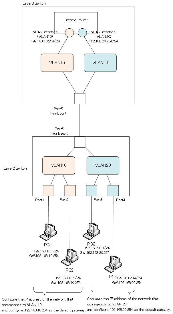
In the figure, VLAN10 and VLAN20 are created by the Layer 2 switch, with PC1 and PC2 belonging to VLAN10 and PC3 and PC4 belonging to VLAN20. And VLAN10 and VLAN20 are interconnected by the Layer 3 switch.
We use a trunk port between the Layer 2 switch and the Layer 3 switch because we need to forward Ethernet frames of VLAN 10 and VLAN 20. Then, create VLAN10 and VLAN20 on the Layer 3 switch side, and configure the VLAN interface on the internal router of the Layer 3 switch to interconnect the two VLANs. The VLAN interface is configured with the IP address of the network address corresponding to each VLAN.
And if we take this network diagram to a simpler logical diagram, it looks like this
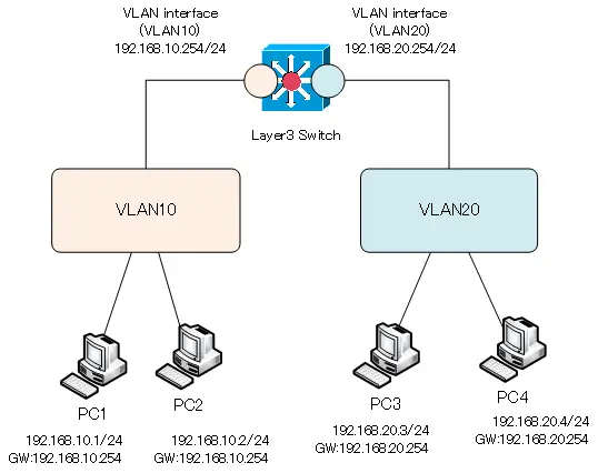
In the logical diagram, you do not need to be particularly aware of the ports of the Layer 2 switch connections. It simply shows how two VLANs, VLAN10 and VLAN20, are interconnected by a Layer 3 switch.
Related article
For more information on configuring Cisco Layer 3 switches, please see the following article.
VLAN(Virtual LAN)
- The need to divide the network
- Details of dividing the network
- VLAN Overview
- VLAN behavior
- Access port : Port assigned to only one VLAN
- Trunk port : Port assigned to multiple VLANs
- Summary of Trunk Protocols – IEEE802.1Q and ISL
- Native VLAN
- Specific example of native VLAN mismatch
- Cisco DTP
- Cisco Configuring and Verifying VLAN
- Cisco VLAN Detailed Configuration Example
- Notes on deleting VLANs
- Voice VLAN – VLAN for connecting IP phones
- VTP :Synchronize VLAN configuration
- VTP pruning – Stopping unnecessary flooding of trunk links
- Configuring and Verifying Cisco VTP
- Inter VLAN routing overview
- Inter-VLAN routing by router
- Inter-VLAN routing by Layer 3 switch
- Configuring and Verifying Inter-VLAN Routing by Cisco Router
- Cisco Configuring Inter-VLAN routing by Layer3 switch : SVI/routed port
- Cisco Layer3 Switch Basic Configuration Example
- Summary of Layer 3 Switch Port Concepts – Access Port/Trunk Port/SVI/Routed Port
- LAN Design pattern : 2-tier and 3-tier