
Table of Contents
What is OSPF area?
An OSPF area is “a group of OSPF routers with the identical LSDB”. By dividing into multiple areas instead of a single area, OSPF can efficiently build routing tables in large networks. The following is a simple example of a multiple area layout.
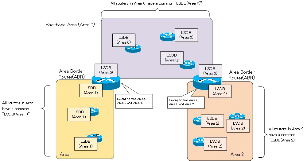
All routers in area 0 have a common “LSDB for area 0”. All routers in area 1 have a common “area 1 LSDB”. Similarly, all routers in area 2 have a common “area 2 LSDB”. A router that interconnects areas is called an Area Border Router (ABR), which belongs to multiple areas and has LSDB for multiple areas.
The OSPF area is identified by a 32-bit area ID. The OSPF area ID can be a simple number, or it can be an 8-bit decimal number like an IP address, “x.x.x.x”.
Recognition of inside and outside the area
OSPF routers understand the network diagram by LSDB. By dividing the network into multiple areas, the degree to which the detailed network diagram is recognized inside and outside the area will differ. In short, “inside the area, in detail; outside the area, just a summary.”
For within an area, understand the network configuration in detail, including how many routers there are and how each router is interconnected. LSAs that describe the detailed network diagram in such an area will not be flowed outside the area. This reduces the exchange of LSAs even in large networks. On the other hand, out of area is only a summary of the network address and the metric to reach it. This means that outside the area does not need to know the network diagram in much detail, and is comparable to a distance-vectored routing protocol such as RIP. Also, for the part of the network that is doing non-OSPF routing (non-OSPF domain), the network address is also known.
When there is a change in the network in an area, it notifies the area and performs SPF calculation to update the routing table if necessary. On the other hand, SPF calculation will not be performed for changes outside the area. By dividing the area, SPF calculations are not performed when networks outside of the area that are not so relevant are changed.
If we focus on the LSDB (Area 1) in “Figure OSPF Area Overview”, it looks like this
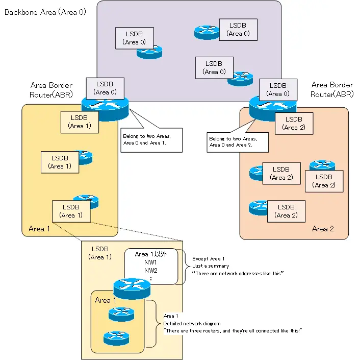
The LSDB (Area 1) describes the details of the network diagram of Area 1. You can see that there are three routers and how each router is connected to each other. You can also see the routers that are ABRs that connect to other areas. For areas other than area 1, this is just an overview of what network addresses are available.
OSPF area is two layers
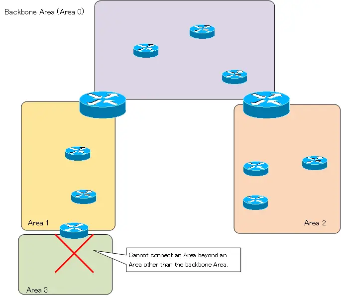
When a network to be routed by OSPF is divided into multiple areas, a two-tiered area layout is taken. The central area is called the backbone area. Area 0 is recognized as the backbone area. All other areas must be connected to the backbone area. As a principle, it is not possible to connect another area beyond the non-backbone area. As shown below, an area layout in which Area 3 is connected to Area 1 is an illegal area layout.
If you must have such an area layout, you can do so by using virtual-link in exceptional cases. However, it is better to consider the area layout that requires a virtual-link as a temporary solution.
Also, multiple backbone areas as shown below are also illegal area layout.
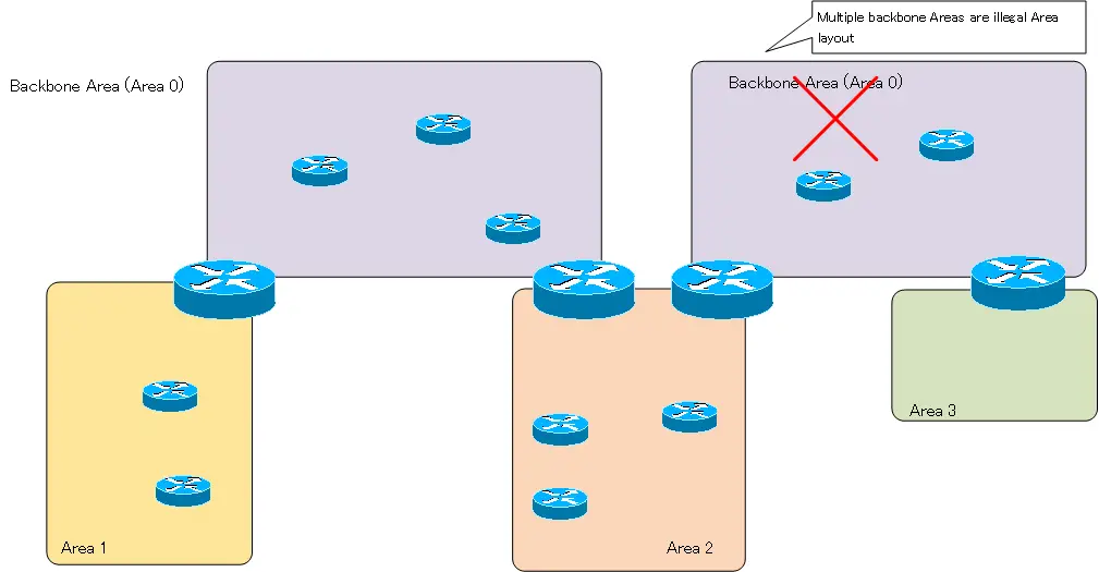
These multiple backbone area layout is called “fragmented backbone” or “discontinuous backbone”. If a discontinuous backbone area layout is used, communication is possible only between the two tiered areas centered on each backbone area, but not for the entire OSPF network. In the above figure, communication between Area 1 and Area 3 is not possible. Also, communication between discontinuous backbone areas is not possible. Virtual-link may be configured to prevent unintentional discontinuous backbone due to link failures.
Example of an area layout for an enterprise network
Since the OSPF area is in principle a two-tiered area centered on the backbone area, the area layout of an enterprise network will often have the part of the WAN that connects the sites as area 0. Then, the network of each site is divided into other areas.
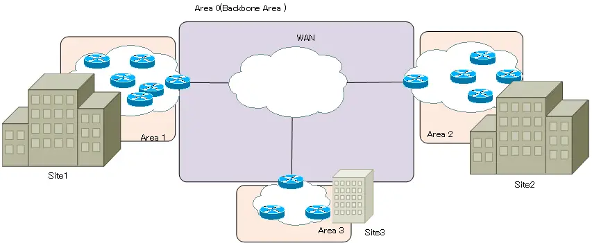
Such an area layout also makes it possible to efficiently summarize the route information of the networks of each site.
Related article
For more information about route summarization in OSPF, please see the following article
Summary
Point
- An OSPF area is a group of routers that have the identical LSDB.
- The details of the network configuration to be grasp are different between inside and outside the area. ” Inside the area, in detail; outside the area, just a summary.”
- The OSPF area must be a two-tiered structure with the backbone area (Area 0) at the center.
- In an enterprise network, the backbone area is the part of the WAN that connects the sites.
How the OSPF works
- OSPF Overview
- OSPF process flow
- OSPF Router ID : Identify OSPF routers
- What if the router ID of the OSPF router is duplicated?
- OSPF Neighbor and Adjacency
- OSPF DR/BDR
- How show ip ospf neighbor looks on Ethernet
- OSPF Network Type : Classification of OSPF-enabled interfaces
- Synchronization process of OSPF LSDB
- Problems with large-scale OSPF network
- OSPF Area – Inside the area, in detail; outside the area, just a summary
- OSPF Router Type
- OSPF LSA Type
- OSPF Area Type
- OSPF Basic Configuration and Verification Commands
- Details of enabling OSPF on the interface
- OSPF Advertising Loopback Interface
- Configuring and Verifying OSPF Hello/Dead interval
- OSPF Cost Configuration and Verification
- Configuring and Verifying OSPF Router Priority
- Configuring OSPF Neighbor Authentication
- Neighbor Authentication over Virtual-link
- OSPF Configuring and Verifying Stub area [Cisco]
- OSPF Stub Area Configuration Example [Cisco]
- OSPF default route generation : default-information originate command
- Configuration Example of OSPF default route generation : stub area
- OSPF Virtual-Link : Virtual area 0 point-to-point link
- Configuring and Verifying OSPF Virtual-link [Cisco]
- OSPF Virtual-link Configuration Example [Cisco]
- OSPF Virtual-link for discontinuous backbone configuration example
- OSPF Route Summary and Configuration
- Cisco OSPF Route Summary Configuration Example
- OSPF Route Type Preference
- Why the OSPF neighbor state gets stuck in Exstart?
- OSPF packet type and header format
- OSPF Hello Packet
- OSPF DD(Database Description) Packet
- OSPF LSR(Link State Request) Packet
- OSPF LSU(Link State Update) Packet
- OSPF LSAck(Link State Acknowledgement) Packet
- Limitation of OSPF redistribution routes – redistribute maximum-prefix command
- Overview of LSA Filters for OSPF – Filter LSA Type 3/Type 5
- Configuration example of LSA type 3 filter
- Configuration example of LSA type 5 filter
- OSPFv3 Configuration Example [Cisco]
- Configuration Example of OSPFv3 Route Summary [Cisco]