Table of Contents
What is DR/BDR ?
DR (Designed Router)/BDR (Backup Designated Router) is a router that is chosen to efficiently synchronize LSDB on a multi-access network such as Ethernet. The DR is an OSPF router representing a multi-access network. And the BDR is the backup of the DR. If the DR goes down, the BDR becomes the next DR. The OSPF router that is neither the DR nor the BDR in a multi-access network is the DROTHER.
This section explains in detail the mechanism of synchronizing LSDB on a multi-access network by DR.
Synchronization of LSDB over Ethernet (multi-access network)
In a multi-access network such as Ethernet, two or more OSPF routers may be connected. Each OSPF router on the multi-access network will then eventually synchronize its LSDB.
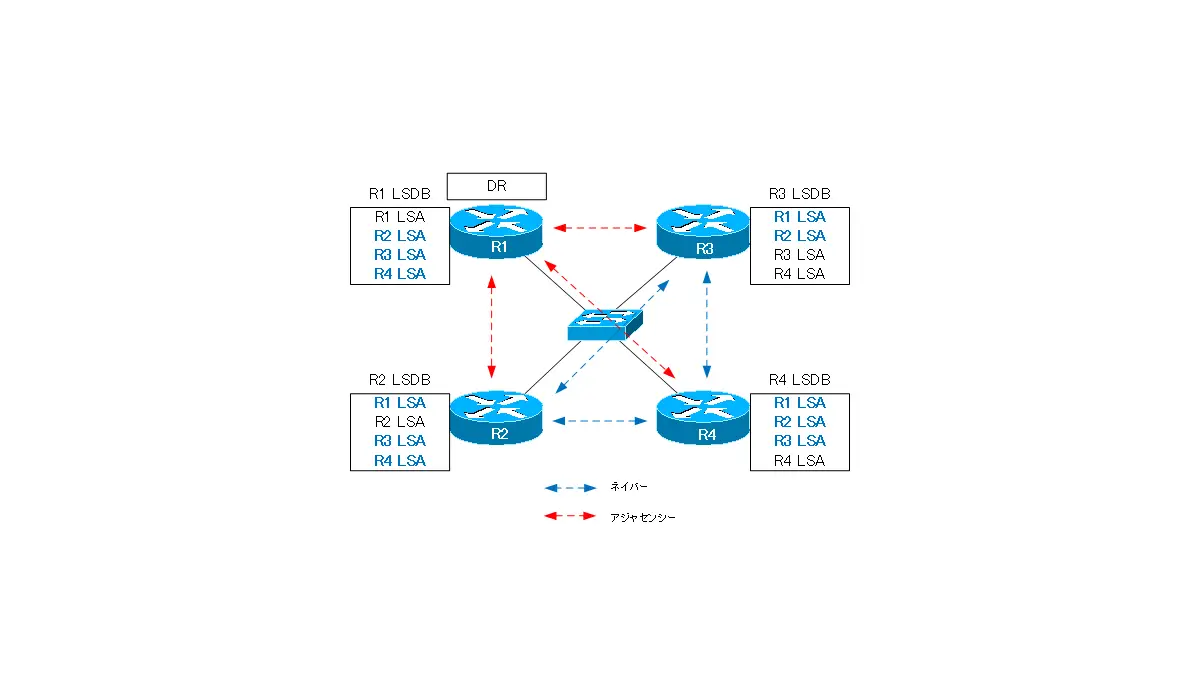
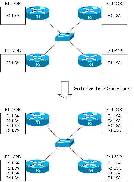
Consider a simple multi-access network example. In the following figure, four OSPF routers, R1 to R4, are connected on the Ethernet. Initially, each router has only its own LSA registered in its LSDB. It will eventually synchronize the LSDB of each router so that all LSAs of R1 to R4 are registered in the LSDB of R1 to R4.
LSDB synchronization via DR
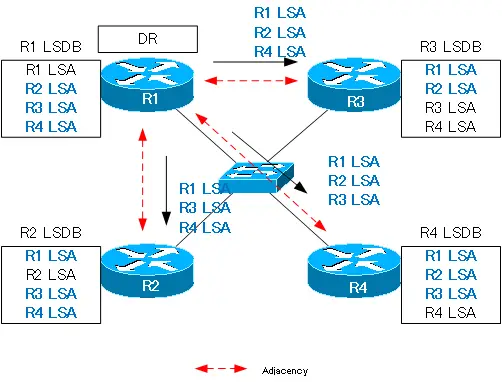
In order to achieve this synchronization, OSPF elects a DR on the multi-access network; it establishes an adjacency between the DR and the OSPF routers on the multi-access network. Each router sends its own LSA to the DR. Each router sends its own LSA to the DR, which means that all LSAs will be gathered in the DR.
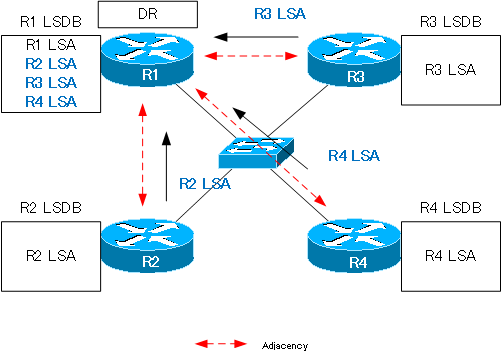
Then, have the DR send the missing LSAs, and finally synchronize the LSDBs of all OSPF routers on the multi-access network.
DR and neighbor/adjacency
The relationship between R1 to R4 neighbors and the adjacency is as follows.
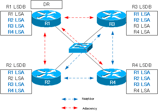
| Router-to-Router Relationship | Inter-router |
| neighbor | R2-R3、R2-R4、R3-R4 |
| adjacency | R1-R2、R1-R3、R1-R4 |
Only the relationship with R1, which is the DR, is an adjacency. All other routers are just neighbors. Routers in a simple neighbor relationship do not exchange LSAs directly with each other, but they ultimately have the same LSDB.
Related article
Please see the following articles about neighbor and adjacency.
See the following article on how Neighbors and Adjacencies look on Ethernet with Cisco routers.
Election of DR/BDR
The election of DR/BDR is done by the following two parameters.
- router priority
- router ID
Router Priority and Router ID are both included in the Hello packet. The router priority is an 8-bit value set for the OSPF interface; in decimal, the value ranges from 0 to 255. The router with the highest router priority value becomes the DR, and the next highest router becomes the BDR. And, Priority “0” means that it will not be DR/BDR.
When the router priority has the same value and DR/BDR cannot be determined by router priority, selection by router ID is performed. The router with the highest router ID becomes the DR, and the router with the next highest router ID becomes the BDR. Since the router ID is unique, the router ID will always determine the DR/BDR in the end.
Related article
For information on configuring Cisco routers to change router priority, see the following article.
Switching DR
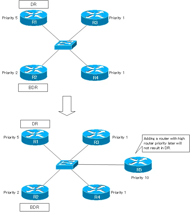
LSDB synchronization is ensured on a multi-access network with the DR at the center; if the DR is changed, LSDB synchronization cannot be maintained and packets can no longer be routed. So, Once a DR/BDR is determined, it is kept as unchanged as possible. Even if a router with a higher router priority is added later, the existing DR/BDR will not change. Also, when a DR goes down, the BDR becomes the new DR.
In the following figure, R1’s router priority is 5, making it a DR, and R2’s router priority is 2, making it a BDR. Even if we add a new R5 with router priority 10, the DR and BDR will not change.
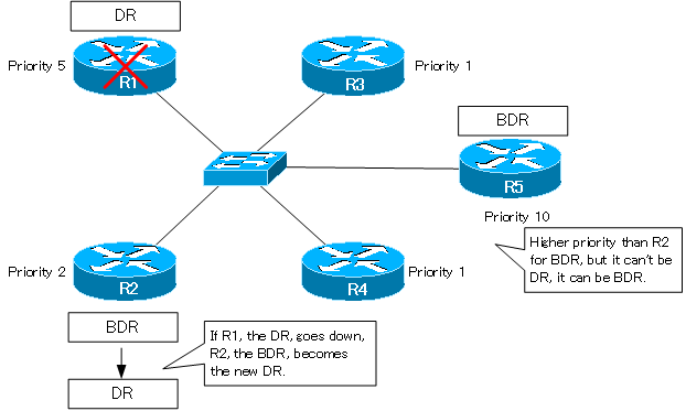
Then, if R1, the DR, goes down, R2, which was the BDR, becomes the new DR. R5 does not become the DR; the BDR is the router that will always become the next DR when the current DR becomes unavailable. In this case, R5 becomes the BDR.
As described above, the behavior is such that as little DR/BDR change as possible will occur. Therefore, when there are multiple OSPF routers in a multi-access network, the order in which the routers are started should be considered, because if the router that you want to be DR starts late, it may not become DR even if its priority is high.
Example of DR election
So far, we have been thinking about DR/BDR using a single Ethernet network as an example. Let’s consider DR election in a more realistic network topology as follows.
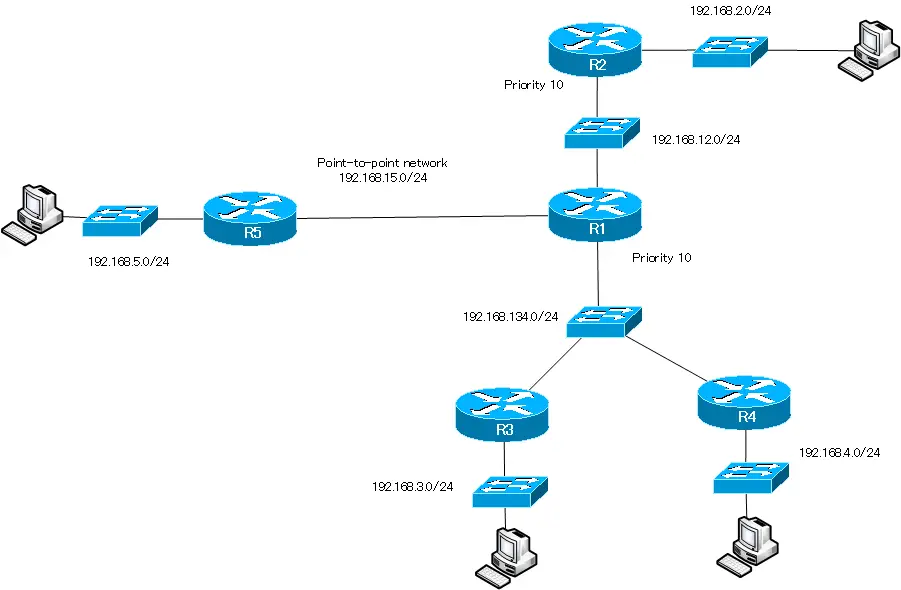
The point-to-point network between R1 and R5 in this figure is a serial connection. Everything else is assumed to be an Ethernet multi-access network. Also, the OSPF router priority is set to 1 for all other parts not shown.
The DR/BDR is elected for each multi-access network. In a point-to-point network, DR/BDR election is not required. In this example, the DR election is as follows.
| Network | DR |
| 192.168.12.0/24 | R2 |
| 192.168.134.0/24 | R1 |
| 192.168.15.0/24 | No Election of DR required (point-to-point) |
| 192.168.2.0/24 | R2 |
| 192.168.3.0/24 | R3 |
| 192.168.4.0/24 | R4 |
| 192.168.5.0/24 | R5 |
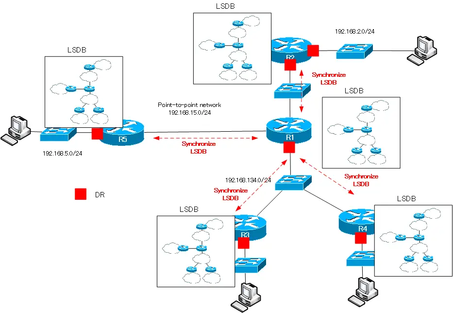
In 192.168.12.0/24, R2 with high router priority is the DR; in 192.168.134.0/24, R1 with high router priority is the DR. Then, in a multiple-access network, it becomes the adjacency and synchronizes the LSDB with the DR. In a point-to-point network, the DR is not elected, but R1 and R5 are the neighbors i.e., they are the adjacency and synchronize the LSDB. Eventually, the LSDBs of all OSPF routers in R1 to R5 will be synchronized.
Summary
Point
- The DR/BDR is a router that is elected to efficiently synchronize the LSDB on a multi-access network such as Ethernet; OSPF router establishes an adjacency with the DR/BDR, exchanges LSAs, and synchronizes the LSDB.
- In point-to-point networks, DR/BDR election is not required.
- DR/BDR is selected by router priority and router ID. If the DR goes down, the BDR becomes the new DR.
How the OSPF works
- OSPF Overview
- OSPF process flow
- OSPF Router ID : Identify OSPF routers
- What if the router ID of the OSPF router is duplicated?
- OSPF Neighbor and Adjacency
- OSPF DR/BDR
- How show ip ospf neighbor looks on Ethernet
- OSPF Network Type : Classification of OSPF-enabled interfaces
- Synchronization process of OSPF LSDB
- Problems with large-scale OSPF network
- OSPF Area – Inside the area, in detail; outside the area, just a summary
- OSPF Router Type
- OSPF LSA Type
- OSPF Area Type
- OSPF Basic Configuration and Verification Commands
- Details of enabling OSPF on the interface
- OSPF Advertising Loopback Interface
- Configuring and Verifying OSPF Hello/Dead interval
- OSPF Cost Configuration and Verification
- Configuring and Verifying OSPF Router Priority
- Configuring OSPF Neighbor Authentication
- Neighbor Authentication over Virtual-link
- OSPF Configuring and Verifying Stub area [Cisco]
- OSPF Stub Area Configuration Example [Cisco]
- OSPF default route generation : default-information originate command
- Configuration Example of OSPF default route generation : stub area
- OSPF Virtual-Link : Virtual area 0 point-to-point link
- Configuring and Verifying OSPF Virtual-link [Cisco]
- OSPF Virtual-link Configuration Example [Cisco]
- OSPF Virtual-link for discontinuous backbone configuration example
- OSPF Route Summary and Configuration
- Cisco OSPF Route Summary Configuration Example
- OSPF Route Type Preference
- Why the OSPF neighbor state gets stuck in Exstart?
- OSPF packet type and header format
- OSPF Hello Packet
- OSPF DD(Database Description) Packet
- OSPF LSR(Link State Request) Packet
- OSPF LSU(Link State Update) Packet
- OSPF LSAck(Link State Acknowledgement) Packet
- Limitation of OSPF redistribution routes – redistribute maximum-prefix command
- Overview of LSA Filters for OSPF – Filter LSA Type 3/Type 5
- Configuration example of LSA type 3 filter
- Configuration example of LSA type 5 filter
- OSPFv3 Configuration Example [Cisco]
- Configuration Example of OSPFv3 Route Summary [Cisco]