Table of Contents
OSPF is enabled on each router interface.
With the exception of BGP, routing protocols such as OSPF and RIP/EIGRP are enabled on a per-router interface basis. Let’s consider “enabling OSPF on the interface” in detail.
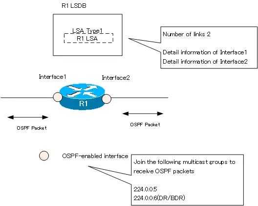
When OSPF is enabled on the router’s interface, the following behavior is taking place.
- Send and receive OSPF packets on the enabled interface
- Register the enabled interface as an OSPF link in the LSDB
Send and receive OSPF packets on the enabled interface
OSPF packets will be sent on the enabled interface. The first step is to send a Hello packet.
Then, in order to receive OSPF packets, the interface is joined to the OSPF multicast address. 224.0.0.5 is a multicast group that represents all OSPF routers, and any interface with OSPF enabled will always join the 224.0.0.5 multicast group. If an OSPF enabled interface is elected as DR/BDR, it will also join the 224.0.0.6 multicast group.
Register the enabled interface as an OSPF link in the LSDB
The OSPF enabled interface will then be registered as an “OSPF link” in the LSA type 1 router LSA, which represents the state of the link for the router. LSAs will be exchanged with other OSPF routers. This means that the information of the OSPF enabled interface will be advertised to other OSPF routers. Note that information for interfaces that do not have OSPF enabled is not advertised.
Simple configuration of OSPF on a Cisco router
Let’s do a simple configuration of OSPF on R1 in the following figure and see what happens when OSPF is enabled on the interface.

Related article
The basic configuration commands for OSPF on Cisco routers are explained in detail in the following article.
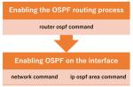
Enable OSPF process
Before enabling OSPF on the interface, you need to enable the OSPF process; enable the OSPF process on R1 and set 1.1.1.1 as the router ID.
R1
router ospf 1
 router-id 1.1.1.1
Just by enabling the OSPF process, no OSPF link exists, so nothing will be registered in the LSDB.
R1
R1#show ip ospf database

            OSPF Router with ID (1.1.1.1) (Process ID 1)
Also, the interface of R1 is not participating in the OSPF multicast group.
Enable OSPF on Fa0/0
Enable OSPF on R1 Fa0/0.
R1
router ospf 1
 network 192.168.1.1 0.0.0.0 area 0
By enabling OSPF on R1 Fa0/0, Fa0/0 will join the multicast groups 224.0.0.5 and 224.0.0.6. There are no other routers connected to Fa0/0, but it is in DR, so it also participates in the 224.0.0.6 multicast group.
R1#show ip ospf interface brief
Interface    PID   Area            IP Address/Mask    Cost  State Nbrs F/C
Fa0/0        1     0               192.168.1.1/24     10    DR    0/0
R1#show ip interface FastEthernet 0/0
FastEthernet0/0 is up, line protocol is up
  Internet address is 192.168.1.1/24
  Broadcast address is 255.255.255.255
  Address determined by setup command
  MTU is 1500 bytes
  Helper address is not set
  Directed broadcast forwarding is disabled
  Multicast reserved groups joined: 224.0.0.5 224.0.0.6
-- omitted --
And when you look at the LSDB, LSA type 1 for R1 is generated; the link count for LSA type 1 is 1.
R1
R1#show ip ospf database

            OSPF Router with ID (1.1.1.1) (Process ID 1)

                Router Link States (Area 0)

Link ID         ADV Router      Age         Seq#       Checksum Link count
1.1.1.1         1.1.1.1         273         0x80000001 0x00E4D1 1
R1#show ip ospf database router 1.1.1.1

            OSPF Router with ID (1.1.1.1) (Process ID 1)

                Router Link States (Area 0)

  LS age: 281
  Options: (No TOS-capability, DC)
  LS Type: Router Links
  Link State ID: 1.1.1.1
  Advertising Router: 1.1.1.1
  LS Seq Number: 80000001
  Checksum: 0xE4D1
  Length: 36
  Number of Links: 1

    Link connected to: a Stub Network
     (Link ID) Network/subnet number: 192.168.1.0
     (Link Data) Network Mask: 255.255.255.0
      Number of TOS metrics: 0
       TOS 0 Metrics: 10
Enable OSPF on Fa0/1
Next, enable OSPF on R1 Fa0/1.
R1
router ospf 1
 network 192.168.2.1 0.0.0.0 area 0
When OSPF is enabled on R1 Fa0/1, Fa0/1 participates in multicast groups 224.0.0.5 and 224.0.0.6.
R1
R1#show ip ospf interface brief
Interface    PID   Area            IP Address/Mask    Cost  State Nbrs F/C
Fa0/1        1     0               192.168.2.1/24     10    DR    0/0
Fa0/0        1     0               192.168.1.1/24     10    DR    0/0
R1#show ip interface FastEthernet 0/1
FastEthernet0/1 is up, line protocol is up
  Internet address is 192.168.2.1/24
  Broadcast address is 255.255.255.255
  Address determined by setup command
  MTU is 1500 bytes
  Helper address is not set
  Directed broadcast forwarding is disabled
  Multicast reserved groups joined: 224.0.0.5 224.0.0.6
~省略~
And the link count for LSA type 1 on R1 is 2. Fa0/1 link information has been added.
R1
R1#show ip ospf database

            OSPF Router with ID (1.1.1.1) (Process ID 1)

                Router Link States (Area 0)

Link ID         ADV Router      Age         Seq#       Checksum Link count
1.1.1.1         1.1.1.1         150         0x80000002 0x001917 2
R1#show ip ospf database router 1.1.1.1

            OSPF Router with ID (1.1.1.1) (Process ID 1)

                Router Link States (Area 0)

  LS age: 157
  Options: (No TOS-capability, DC)
  LS Type: Router Links
  Link State ID: 1.1.1.1
  Advertising Router: 1.1.1.1
  LS Seq Number: 80000002
  Checksum: 0x1917
  Length: 48
  Number of Links: 2

    Link connected to: a Stub Network
     (Link ID) Network/subnet number: 192.168.2.0
     (Link Data) Network Mask: 255.255.255.0
      Number of TOS metrics: 0
       TOS 0 Metrics: 10

    Link connected to: a Stub Network
     (Link ID) Network/subnet number: 192.168.1.0
     (Link Data) Network Mask: 255.255.255.0
      Number of TOS metrics: 0
       TOS 0 Metrics: 10
Summary
Point
- Be properly aware that routing protocols such as OSPF should be “enabled on each router interface”.
- When OSPF is enabled on the router interface, the following is done
- Send and receive OSPF packets on the enabled interface
- Register the enabled interface as an OSPF link in the LSDB
How the OSPF works
- OSPF Overview
- OSPF process flow
- OSPF Router ID : Identify OSPF routers
- What if the router ID of the OSPF router is duplicated?
- OSPF Neighbor and Adjacency
- OSPF DR/BDR
- How show ip ospf neighbor looks on Ethernet
- OSPF Network Type : Classification of OSPF-enabled interfaces
- Synchronization process of OSPF LSDB
- Problems with large-scale OSPF network
- OSPF Area – Inside the area, in detail; outside the area, just a summary
- OSPF Router Type
- OSPF LSA Type
- OSPF Area Type
- OSPF Basic Configuration and Verification Commands
- Details of enabling OSPF on the interface
- OSPF Advertising Loopback Interface
- Configuring and Verifying OSPF Hello/Dead interval
- OSPF Cost Configuration and Verification
- Configuring and Verifying OSPF Router Priority
- Configuring OSPF Neighbor Authentication
- Neighbor Authentication over Virtual-link
- OSPF Configuring and Verifying Stub area [Cisco]
- OSPF Stub Area Configuration Example [Cisco]
- OSPF default route generation : default-information originate command
- Configuration Example of OSPF default route generation : stub area
- OSPF Virtual-Link : Virtual area 0 point-to-point link
- Configuring and Verifying OSPF Virtual-link [Cisco]
- OSPF Virtual-link Configuration Example [Cisco]
- OSPF Virtual-link for discontinuous backbone configuration example
- OSPF Route Summary and Configuration
- Cisco OSPF Route Summary Configuration Example
- OSPF Route Type Preference
- Why the OSPF neighbor state gets stuck in Exstart?
- OSPF packet type and header format
- OSPF Hello Packet
- OSPF DD(Database Description) Packet
- OSPF LSR(Link State Request) Packet
- OSPF LSU(Link State Update) Packet
- OSPF LSAck(Link State Acknowledgement) Packet
- Limitation of OSPF redistribution routes – redistribute maximum-prefix command
- Overview of LSA Filters for OSPF – Filter LSA Type 3/Type 5
- Configuration example of LSA type 3 filter
- Configuration example of LSA type 5 filter
- OSPFv3 Configuration Example [Cisco]
- Configuration Example of OSPFv3 Route Summary [Cisco]