Table of Contents
Overview
A link failure in the backbone area may result in a discontinuous backbone. In such a case, Virtual-link can be used to configure the backbone area to be continuous.
Related article
The following articles explain the uses of virtual-links and the configuration commands on Cisco routers.

Network Diagram
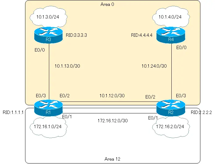
Configuration Condition
- If R1 E0/2 is administratively shut down, communication between 10.1.3.0/24 and 10.1.4.0/24 will not be possible. Perform the necessary configurations so that communication between 10.1.3.0/24 and 10.1.4.0/24 will be possible even if R1 E0/2 is shut down.
Verification Condition
- Communication between 10.1.3.0/24 and 10.1.4.0/24 is possible even if R1 E0/2 is shut down.
Initial Configuration
The following configurations are assumed to be already configured.
- Hostname
- IP Address
- OSPF
- Router ID
- Each router interface has OSPF enabled and belongs to an area as shown in the network diagram.
Configuration
Step1: Verifying the routing table under normal conditions
Verify the routing table under normal conditions on each router of R1 to R4.
R1 show ip route
R1#show ip route
-- omitted --

Gateway of last resort is not set

     172.16.0.0/16 is variably subnetted, 3 subnets, 2 masks
C       172.16.12.0/30 is directly connected, Ethernet0/1
C       172.16.1.0/24 is directly connected, Ethernet0/0
O       172.16.2.0/24 [110/20] via 172.16.12.2, 00:08:29, Ethernet0/1
     10.0.0.0/8 is variably subnetted, 5 subnets, 2 masks
C       10.1.13.0/30 is directly connected, Ethernet0/3
C       10.1.12.0/30 is directly connected, Ethernet0/2
O       10.1.3.0/24 [110/20] via 10.1.13.2, 00:06:00, Ethernet0/3
O       10.1.4.0/24 [110/30] via 10.1.12.2, 00:06:00, Ethernet0/2
O       10.1.24.0/30 [110/20] via 10.1.12.2, 00:06:00, Ethernet0/2
R2 show ip route
R2#show ip route
-- omitted --

Gateway of last resort is not set

     172.16.0.0/16 is variably subnetted, 3 subnets, 2 masks
C       172.16.12.0/30 is directly connected, Ethernet0/1
O       172.16.1.0/24 [110/20] via 172.16.12.1, 00:08:59, Ethernet0/1
C       172.16.2.0/24 is directly connected, Ethernet0/0
     10.0.0.0/8 is variably subnetted, 5 subnets, 2 masks
O       10.1.13.0/30 [110/20] via 10.1.12.1, 00:06:49, Ethernet0/2
C       10.1.12.0/30 is directly connected, Ethernet0/2
O       10.1.3.0/24 [110/30] via 10.1.12.1, 00:06:49, Ethernet0/2
O       10.1.4.0/24 [110/20] via 10.1.24.2, 00:06:49, Ethernet0/3
C       10.1.24.0/30 is directly connected, Ethernet0/3
R3 show ip route
R3#show ip route
-- omitted --

Gateway of last resort is not set

     172.16.0.0/16 is variably subnetted, 3 subnets, 2 masks
O IA    172.16.12.0/30 [110/20] via 10.1.13.1, 00:07:23, Ethernet0/0
O IA    172.16.1.0/24 [110/20] via 10.1.13.1, 00:07:23, Ethernet0/0
O IA    172.16.2.0/24 [110/30] via 10.1.13.1, 00:07:23, Ethernet0/0
     10.0.0.0/8 is variably subnetted, 5 subnets, 2 masks
C       10.1.13.0/30 is directly connected, Ethernet0/0
O       10.1.12.0/30 [110/20] via 10.1.13.1, 00:07:23, Ethernet0/0
C       10.1.3.0/24 is directly connected, Ethernet0/1
O       10.1.4.0/24 [110/40] via 10.1.13.1, 00:07:23, Ethernet0/0
O       10.1.24.0/30 [110/30] via 10.1.13.1, 00:07:23, Ethernet0/0
R4 show ip route
R4#show ip route
-- omitted --

Gateway of last resort is not set

     172.16.0.0/16 is variably subnetted, 3 subnets, 2 masks
O IA    172.16.12.0/30 [110/20] via 10.1.24.1, 00:08:00, Ethernet0/0
O IA    172.16.1.0/24 [110/30] via 10.1.24.1, 00:08:00, Ethernet0/0
O IA    172.16.2.0/24 [110/20] via 10.1.24.1, 00:08:00, Ethernet0/0
     10.0.0.0/8 is variably subnetted, 5 subnets, 2 masks
O       10.1.13.0/30 [110/30] via 10.1.24.1, 00:08:00, Ethernet0/0
O       10.1.12.0/30 [110/20] via 10.1.24.1, 00:08:00, Ethernet0/0
O       10.1.3.0/24 [110/40] via 10.1.24.1, 00:08:00, Ethernet0/0
C       10.1.4.0/24 is directly connected, Ethernet0/1
C       10.1.24.0/30 is directly connected, Ethernet0/0
Step2: Shutdown of R1 E0/2
Shut down R1 E0/2 and investigate the cause of the failure of communication between 10.1.3.0/24 and 10.1.4.0/24.
R1
interface Ethernet0/2
 shutdown
Step3: Verifying the routing table during R1 E0/2 shutdown
Verify the routing table of each router when R1 E0/2 is shut down.
R1 show ip route
R1#show ip route
-- omitted --

Gateway of last resort is not set

     172.16.0.0/16 is variably subnetted, 3 subnets, 2 masks
C       172.16.12.0/30 is directly connected, Ethernet0/1
C       172.16.1.0/24 is directly connected, Ethernet0/0
O       172.16.2.0/24 [110/20] via 172.16.12.2, 00:12:55, Ethernet0/1
     10.0.0.0/8 is variably subnetted, 2 subnets, 2 masks
C       10.1.13.0/30 is directly connected, Ethernet0/3
O       10.1.3.0/24 [110/20] via 10.1.13.2, 00:00:06, Ethernet0/3
R2 show ip route
R2#show ip route
-- omitted --

Gateway of last resort is not set

     172.16.0.0/16 is variably subnetted, 3 subnets, 2 masks
C       172.16.12.0/30 is directly connected, Ethernet0/1
O       172.16.1.0/24 [110/20] via 172.16.12.1, 00:15:10, Ethernet0/1
C       172.16.2.0/24 is directly connected, Ethernet0/0
     10.0.0.0/8 is variably subnetted, 3 subnets, 2 masks
C       10.1.12.0/30 is directly connected, Ethernet0/2
O       10.1.4.0/24 [110/20] via 10.1.24.2, 00:01:58, Ethernet0/3
C       10.1.24.0/30 is directly connected, Ethernet0/3
R3 show ip route
R3#show ip route
-- omitted --

Gateway of last resort is not set

     172.16.0.0/16 is variably subnetted, 3 subnets, 2 masks
O IA    172.16.12.0/30 [110/20] via 10.1.13.1, 00:00:49, Ethernet0/0
O IA    172.16.1.0/24 [110/20] via 10.1.13.1, 00:00:49, Ethernet0/0
O IA    172.16.2.0/24 [110/30] via 10.1.13.1, 00:00:49, Ethernet0/0
     10.0.0.0/8 is variably subnetted, 2 subnets, 2 masks
C       10.1.13.0/30 is directly connected, Ethernet0/0
C       10.1.3.0/24 is directly connected, Ethernet0/1
R4 show ip route
R4#show ip route
-- omitted --

Gateway of last resort is not set

     172.16.0.0/16 is variably subnetted, 3 subnets, 2 masks
O IA    172.16.12.0/30 [110/20] via 10.1.24.1, 00:02:42, Ethernet0/0
O IA    172.16.1.0/24 [110/30] via 10.1.24.1, 00:02:42, Ethernet0/0
O IA    172.16.2.0/24 [110/20] via 10.1.24.1, 00:02:42, Ethernet0/0
     10.0.0.0/8 is variably subnetted, 3 subnets, 2 masks
O       10.1.12.0/30 [110/20] via 10.1.24.1, 00:02:42, Ethernet0/0
C       10.1.4.0/24 is directly connected, Ethernet0/1
C       10.1.24.0/30 is directly connected, Ethernet0/0
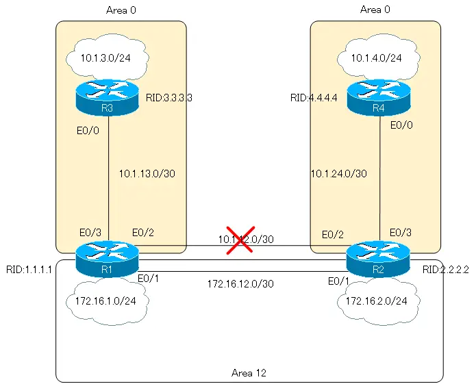
When R1 E0/2 is shut down, Area 0 becomes discontinuous. As a result, routes in the discontiguous backbone area will not be registered in the routing table. For example, the following routes that existed under normal conditions will no longer exist in the routing table of R1.
- 10.1.24.0/30
- 10.1.4.0/24
If the route does not exist in the routing table, of course routing will not be possible.
Step4: Configuring Virtual-Link
To resolve the discontinuous backbone, configure virtual-link between R1 and R2.
R1
router ospf 1
 area 12 virtual-link 2.2.2.2
R2
router ospf 1
 area 12 virtual-link 1.1.1.1
Step5: Verify Virtual-Link.
Use the show ip ospf virtual-links command to verify virtual-link between R1 and R2.
R1 show ip ospf virtual-links
R1#show ip ospf virtual-links
Virtual Link OSPF_VL0 to router 2.2.2.2 is up
  Run as demand circuit
  DoNotAge LSA allowed.
  Transit area 12, via interface Ethernet0/1, Cost of using 10
  Transmit Delay is 1 sec, State POINT_TO_POINT,
  Timer intervals configured, Hello 10, Dead 40, Wait 40, Retransmit 5
    Hello due in 00:00:08
    Adjacency State FULL (Hello suppressed)
    Index 1/2, retransmission queue length 0, number of retransmission 0
    First 0x0(0)/0x0(0) Next 0x0(0)/0x0(0)
    Last retransmission scan length is 0, maximum is 0
    Last retransmission scan time is 0 msec, maximum is 0 msec
R2 show ip ospf virtual-links
R2#show ip ospf virtual-links
Virtual Link OSPF_VL0 to router 1.1.1.1 is up
  Run as demand circuit
  DoNotAge LSA allowed.
  Transit area 12, via interface Ethernet0/1, Cost of using 10
  Transmit Delay is 1 sec, State POINT_TO_POINT,
  Timer intervals configured, Hello 10, Dead 40, Wait 40, Retransmit 5
    Hello due in 00:00:08
    Adjacency State FULL (Hello suppressed)
    Index 1/2, retransmission queue length 0, number of retransmission 0
    First 0x0(0)/0x0(0) Next 0x0(0)/0x0(0)
    Last retransmission scan length is 0, maximum is 0
    Last retransmission scan time is 0 msec, maximum is 0 msec
Step6: Verifying the routing table when Virtual-Link is configured
Verify the routing table of each router after configuring virtual-link between R1 and R2.
R1 show ip route
R1#show ip route
-- omitted --

Gateway of last resort is not set

     172.16.0.0/16 is variably subnetted, 3 subnets, 2 masks
C       172.16.12.0/30 is directly connected, Ethernet0/1
C       172.16.1.0/24 is directly connected, Ethernet0/0
O       172.16.2.0/24 [110/20] via 172.16.12.2, 00:05:23, Ethernet0/1
     10.0.0.0/8 is variably subnetted, 5 subnets, 2 masks
C       10.1.13.0/30 is directly connected, Ethernet0/3
O       10.1.12.0/30 [110/20] via 172.16.12.2, 00:05:23, Ethernet0/1
O       10.1.3.0/24 [110/20] via 10.1.13.2, 00:05:23, Ethernet0/3
O       10.1.4.0/24 [110/30] via 172.16.12.2, 00:05:23, Ethernet0/1
O       10.1.24.0/30 [110/20] via 172.16.12.2, 00:05:23, Ethernet0/1
R2 show ip route
R2#show ip route
-- omitted --

Gateway of last resort is not set

     172.16.0.0/16 is variably subnetted, 3 subnets, 2 masks
C       172.16.12.0/30 is directly connected, Ethernet0/1
O       172.16.1.0/24 [110/20] via 172.16.12.1, 00:05:47, Ethernet0/1
C       172.16.2.0/24 is directly connected, Ethernet0/0
     10.0.0.0/8 is variably subnetted, 5 subnets, 2 masks
O       10.1.13.0/30 [110/20] via 172.16.12.1, 00:05:47, Ethernet0/1
C       10.1.12.0/30 is directly connected, Ethernet0/2
O       10.1.3.0/24 [110/30] via 172.16.12.1, 00:05:47, Ethernet0/1
O       10.1.4.0/24 [110/20] via 10.1.24.2, 00:05:47, Ethernet0/3
C       10.1.24.0/30 is directly connected, Ethernet0/3
R3 show ip route
R3#show ip route
-- omitted --

Gateway of last resort is not set

     172.16.0.0/16 is variably subnetted, 3 subnets, 2 masks
O IA    172.16.12.0/30 [110/20] via 10.1.13.1, 00:06:14, Ethernet0/0
O IA    172.16.1.0/24 [110/20] via 10.1.13.1, 00:06:14, Ethernet0/0
O IA    172.16.2.0/24 [110/30] via 10.1.13.1, 00:06:14, Ethernet0/0
     10.0.0.0/8 is variably subnetted, 5 subnets, 2 masks
C       10.1.13.0/30 is directly connected, Ethernet0/0
O       10.1.12.0/30 [110/30] via 10.1.13.1, 00:06:14, Ethernet0/0
C       10.1.3.0/24 is directly connected, Ethernet0/1
O       10.1.4.0/24 [110/40] via 10.1.13.1, 00:06:14, Ethernet0/0
O       10.1.24.0/30 [110/30] via 10.1.13.1, 00:06:14, Ethernet0/0
R4 show ip route
R4#show ip route
-- omitted --

Gateway of last resort is not set

     172.16.0.0/16 is variably subnetted, 3 subnets, 2 masks
O IA    172.16.12.0/30 [110/20] via 10.1.24.1, 00:06:41, Ethernet0/0
O IA    172.16.1.0/24 [110/30] via 10.1.24.1, 00:06:41, Ethernet0/0
O IA    172.16.2.0/24 [110/20] via 10.1.24.1, 00:06:41, Ethernet0/0
     10.0.0.0/8 is variably subnetted, 5 subnets, 2 masks
O       10.1.13.0/30 [110/30] via 10.1.24.1, 00:06:41, Ethernet0/0
O       10.1.12.0/30 [110/20] via 10.1.24.1, 00:06:41, Ethernet0/0
O       10.1.3.0/24 [110/40] via 10.1.24.1, 00:06:41, Ethernet0/0
C       10.1.4.0/24 is directly connected, Ethernet0/1
C       10.1.24.0/30 is directly connected, Ethernet0/0
By configuring Virtual-link between R1 and R2, the discontinuous backbone has been resolved. Therefore, you can see that the route information for the communication between R3 and R4 is also properly registered.
Final configuration excerpt
The followings are excerpts from the OSPF-related configuration of each router.
R1
hostname R1
!
interface Ethernet0/0
 ip address 172.16.1.1 255.255.255.0
!
interface Ethernet0/1
 ip address 172.16.12.1 255.255.255.252
!
interface Ethernet0/2
 ip address 10.1.12.1 255.255.255.252
 shutdown
!
interface Ethernet0/3
 ip address 10.1.13.1 255.255.255.252
!
router ospf 1
 router-id 1.1.1.1
 log-adjacency-changes
 area 12 virtual-link 2.2.2.2
 network 10.0.0.0 0.255.255.255 area 0
 network 172.16.0.0 0.0.255.255 area 12
R2
hostname R2
!
interface Ethernet0/0
 ip address 172.16.2.2 255.255.255.0
!
interface Ethernet0/1
 ip address 172.16.12.2 255.255.255.252
!
interface Ethernet0/2
 ip address 10.1.12.2 255.255.255.252
!
interface Ethernet0/3
 ip address 10.1.24.1 255.255.255.252
!
router ospf 1
 router-id 2.2.2.2
 log-adjacency-changes
 area 12 virtual-link 1.1.1.1
 network 10.0.0.0 0.255.255.255 area 0
 network 172.16.0.0 0.0.255.255 area 12
R3
hostname R3
!
interface Ethernet0/0
 ip address 10.1.13.2 255.255.255.252
!
interface Ethernet0/1
 ip address 10.1.3.3 255.255.255.0
!
router ospf 1
 router-id 3.3.3.3
 log-adjacency-changes
 network 10.0.0.0 0.255.255.255 area 0
R4
hostname R4
!
interface Ethernet0/0
 ip address 10.1.24.2 255.255.255.252
!
interface Ethernet0/1
 ip address 10.1.4.4 255.255.255.0
!
router ospf 1
 router-id 4.4.4.4
 log-adjacency-changes
 network 10.0.0.0 0.255.255.255 area 0
How the OSPF works
- OSPF Overview
- OSPF process flow
- OSPF Router ID : Identify OSPF routers
- What if the router ID of the OSPF router is duplicated?
- OSPF Neighbor and Adjacency
- OSPF DR/BDR
- How show ip ospf neighbor looks on Ethernet
- OSPF Network Type : Classification of OSPF-enabled interfaces
- Synchronization process of OSPF LSDB
- Problems with large-scale OSPF network
- OSPF Area – Inside the area, in detail; outside the area, just a summary
- OSPF Router Type
- OSPF LSA Type
- OSPF Area Type
- OSPF Basic Configuration and Verification Commands
- Details of enabling OSPF on the interface
- OSPF Advertising Loopback Interface
- Configuring and Verifying OSPF Hello/Dead interval
- OSPF Cost Configuration and Verification
- Configuring and Verifying OSPF Router Priority
- Configuring OSPF Neighbor Authentication
- Neighbor Authentication over Virtual-link
- OSPF Configuring and Verifying Stub area [Cisco]
- OSPF Stub Area Configuration Example [Cisco]
- OSPF default route generation : default-information originate command
- Configuration Example of OSPF default route generation : stub area
- OSPF Virtual-Link : Virtual area 0 point-to-point link
- Configuring and Verifying OSPF Virtual-link [Cisco]
- OSPF Virtual-link Configuration Example [Cisco]
- OSPF Virtual-link for discontinuous backbone configuration example
- OSPF Route Summary and Configuration
- Cisco OSPF Route Summary Configuration Example
- OSPF Route Type Preference
- Why the OSPF neighbor state gets stuck in Exstart?
- OSPF packet type and header format
- OSPF Hello Packet
- OSPF DD(Database Description) Packet
- OSPF LSR(Link State Request) Packet
- OSPF LSU(Link State Update) Packet
- OSPF LSAck(Link State Acknowledgement) Packet
- Limitation of OSPF redistribution routes – redistribute maximum-prefix command
- Overview of LSA Filters for OSPF – Filter LSA Type 3/Type 5
- Configuration example of LSA type 3 filter
- Configuration example of LSA type 5 filter
- OSPFv3 Configuration Example [Cisco]
- Configuration Example of OSPFv3 Route Summary [Cisco]
