Table of Contents
Summary
This is an example of configuring OSPF virtual-link on Cisco routers. The virtual-link provides a virtual connection to the backbone area.
Related article
Please also read the following articles about the uses of virtual-link and the configuration and verification commands in Cisco.
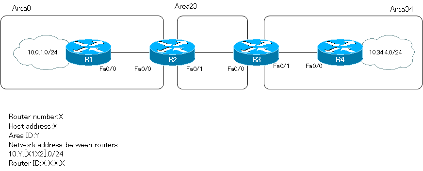
Network Diagram
Initial Configuration
Proceed from the completed configuration in the area shown in the network diagram.
Configuration and Verification
Step1:Routing table before configuring virtual-link
Verify the routing table before configuring the virtual-link. If you use the show ip route command on R1 in area 0, you will see the following
R1
R1#show ip route
-- omitted --

Gateway of last resort is not set

     10.0.0.0/24 is subnetted, 3 subnets
C       10.0.12.0 is directly connected, FastEthernet0/0
O IA    10.23.23.0 [110/20] via 10.0.12.2, 00:00:01, FastEthernet0/0
C       10.0.1.0 is directly connected, Loopback0
Before configuring virtual-link, it is not able to learn the route information for Area 34 that is not connected to Area 0. Naturally, communication with the Area 34 network is not possible.
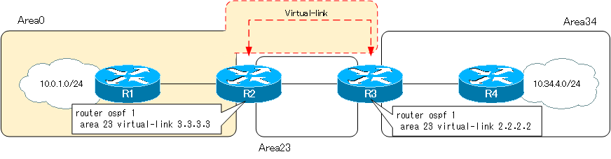
Step2:Configuring Virtual-link
Configure virtual-link to connect area 34 to the backbone area. The routers to configure virtual-link are R2 and R3. Area 23, to which R2 and R3, which configure virtual-link, commonly belong, is the transit area.
R2
router ospf 1
 area 23 virtual-link 3.3.3.3
R3
router ospf 1
 area 23 virtual-link 2.2.2.2
Step3:Verifying Virtual-link
Verify that virtual-link is functioning properly. Look at the show ip ospf virtul-links command on R2.
R2
R2#show ip ospf virtual-links
Virtual Link OSPF_VL0 to router 3.3.3.3 is up
  Run as demand circuit
  DoNotAge LSA allowed.
  Transit area 23, via interface FastEthernet0/1, Cost of using 10
  Transmit Delay is 1 sec, State POINT_TO_POINT,
  Timer intervals configured, Hello 10, Dead 40, Wait 40, Retransmit 5
    Hello due in 00:00:08
    Adjacency State FULL (Hello suppressed)
    Index 2/3, retransmission queue length 0, number of retransmission 0
    First 0x0(0)/0x0(0) Next 0x0(0)/0x0(0)
    Last retransmission scan length is 0, maximum is 0
    Last retransmission scan time is 0 msec, maximum is 0 msec
By establishing virtual-link between R2 and R3, Area 0 will be extended. Area 34 will also be connected to Area 0, and the routes in Area 34 can be learned successfully. Pinging from R1 to 10.34.4.0/24 in area 34 will return a response.
R1
R1#show ip route
-- omitted --

Gateway of last resort is not set

     10.0.0.0/24 is subnetted, 5 subnets
C       10.0.12.0 is directly connected, FastEthernet0/0
O IA    10.34.34.0 [110/30] via 10.0.12.2, 00:07:02, FastEthernet0/0
O IA    10.23.23.0 [110/20] via 10.0.12.2, 00:19:33, FastEthernet0/0
C       10.0.1.0 is directly connected, Loopback0
O IA    10.34.4.0 [110/31] via 10.0.12.2, 00:07:02, FastEthernet0/0
R1#ping 10.34.4.4 source 10.0.1.1

Type escape sequence to abort.
Sending 5, 100-byte ICMP Echos to 10.34.4.4, timeout is 2 seconds:
Packet sent with a source address of 10.0.1.1
!!!!!
Success rate is 100 percent (5/5), round-trip min/avg/max = 64/84/96 ms
How the OSPF works
- OSPF Overview
- OSPF process flow
- OSPF Router ID : Identify OSPF routers
- What if the router ID of the OSPF router is duplicated?
- OSPF Neighbor and Adjacency
- OSPF DR/BDR
- How show ip ospf neighbor looks on Ethernet
- OSPF Network Type : Classification of OSPF-enabled interfaces
- Synchronization process of OSPF LSDB
- Problems with large-scale OSPF network
- OSPF Area – Inside the area, in detail; outside the area, just a summary
- OSPF Router Type
- OSPF LSA Type
- OSPF Area Type
- OSPF Basic Configuration and Verification Commands
- Details of enabling OSPF on the interface
- OSPF Advertising Loopback Interface
- Configuring and Verifying OSPF Hello/Dead interval
- OSPF Cost Configuration and Verification
- Configuring and Verifying OSPF Router Priority
- Configuring OSPF Neighbor Authentication
- Neighbor Authentication over Virtual-link
- OSPF Configuring and Verifying Stub area [Cisco]
- OSPF Stub Area Configuration Example [Cisco]
- OSPF default route generation : default-information originate command
- Configuration Example of OSPF default route generation : stub area
- OSPF Virtual-Link : Virtual area 0 point-to-point link
- Configuring and Verifying OSPF Virtual-link [Cisco]
- OSPF Virtual-link Configuration Example [Cisco]
- OSPF Virtual-link for discontinuous backbone configuration example
- OSPF Route Summary and Configuration
- Cisco OSPF Route Summary Configuration Example
- OSPF Route Type Preference
- Why the OSPF neighbor state gets stuck in Exstart?
- OSPF packet type and header format
- OSPF Hello Packet
- OSPF DD(Database Description) Packet
- OSPF LSR(Link State Request) Packet
- OSPF LSU(Link State Update) Packet
- OSPF LSAck(Link State Acknowledgement) Packet
- Limitation of OSPF redistribution routes – redistribute maximum-prefix command
- Overview of LSA Filters for OSPF – Filter LSA Type 3/Type 5
- Configuration example of LSA type 3 filter
- Configuration example of LSA type 5 filter
- OSPFv3 Configuration Example [Cisco]
- Configuration Example of OSPFv3 Route Summary [Cisco]