Table of Contents
Basic OSPF configuration procedure
There are two basic configuration procedures for OSPF
- Enabling the OSPF routing process
- Enabling OSPF on the interface
There are many other configurations, but these two steps are enough to get the basic OSPF configuration done.
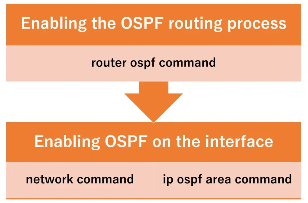
Enabling the OSPF routing process
To enable the OSPF routing process, enter the following command in global configuration mode.
(config)#router ospf <process-id>
(config-router)#
<process-id> : OSPF process id
The process number can be any number from 1 to 65535. a single router can start multiple OSPF processes and the process number is used to identify the OSPF processes locally on the router. However, unless there is a special reason to do so, multiple OSPF processes will not be started.
Since it is used router-local, there is no need to match it with other routers. However, if the process numbers are different for each router, it is difficult to understand the settings, so it is common to use the same process number.
Enabling OSPF on the interface
And there are two ways to enable OSPF on an interface. The configuration we have been using for some time is the configuration of the network command in OSPF configuration mode.
(config-router)#network <ip-address> <wildcardmask> area <area-id>
<ip-address> : IP address
<wildcardmask> : wildcard mask
<area-id> : area id
A combination <ip-address> <wildcardmask> of specifies the bit pattern of the IP address set for the interface on which you want to enable OSPF. For example, “192.168.0.0 0.0.255.255” means that the interface has an IP address of “192.168” in the first 16 bits. You enable OSPF on the interface, but in the configuration, you have to specify “the bit pattern of the IP address set for the interface” rather than the interface name. Then you specify the area id to which the OSPF-enabled interface belongs.
Another way to configure OSPF is to configure the ip ospf area command in interface configuration mode for the interface on which you want OSPF to be enabled.
(config-if)#ip ospf <process-id> area <area-id>
<process-id> : OSPF process id
<area-id> : area id
Whichever configuration method you use, be sure to keep in mind that you are enabling OSPF on the interface.
If you want to configure ABR in multiple areas, you only need to configure the interfaces for area 0 and the other areas.
OSPF configuration example
The following is an example of an OSPF configuration for a simple network diagram.
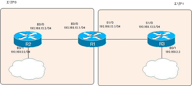
R1 configuration
R1 is ABR. “network 192.168.12.0 0.0.0.255 area 0” means to enable OSPF on the interface with the IP address “192.168.12.x (x: any)” and make it belong to area 0. In other words, we enable OSPF on E0/0 and make it the interface of Area 0. And “network 192.168.13.1 0.0.0.0 area 1” is configured to enable OSPF on the interface of IP address “192.168.13.1”, i.e., S1/0, to make it the interface of area 1.
R1(ABR)
router ospf 1
 network 192.168.12.0 0.0.0.255 area 0
 network 192.168.13.1 0.0.0.0 area 1
R2 configuration
R2 is an example of how to enable OSPF in interface configuration mode. we have enabled OSPF on two interfaces, E0/0 and E0/1, to belong to area 0.
R2
interface Ethernet 0/0
 ip ospf 1 area 0
!
interface Ethernet 0/1
 ip ospf 1 area 0
!
router ospf 1
R3 configuration
And in R3, this is an example of two interfaces, E0/1 and S1/0, enabled with a single line of the network command with a wildcard mask specification. The “network 192.168.0.0 0.0.0.255.255 area 1” is for the interface with the IP address “192.168.x.x (x: any)”. In other words, it specifies two interfaces, E0/1 and S1/0, at once.
R3
router ospf 1
 network 192.168.0.0 0.0.255.255 area 1
The OSPF process numbers are all set to 1 in common. This is for clarity, and it doesn’t matter if the process numbers are not the same.
OSPF Verification commands
The table below summarizes the main commands used to verify the operation of OSPF.
| Verification commands | Summary |
| #show ip protocols | Displays general information about the routing protocol. |
| #show ip ospf | Displays general information about the OSPF. |
| #show ip ospf interface [brief] | Displays information on OSPF-enabled interfaces. |
| #show ip ospf neighbor | Displays OSPF neighbors. |
| #show ip ospf database | Displays OSPF LSDB. |
| #show ip route ospf | Displays the OSPF route of the routing table. |
| #debug ip ospf hello | Displays the exchange of hello packets. |
| #debug ip ospf adj | Displays the LSDB synchronization process. |
show ip protocols
The show ip protocols command displays general information about the routing protocol, not just OSPF. for OSPF, you can verify the process number, router IDs, the network command configurations, and the numerator value of the cost formula.
R1#show ip protocols
Routing Protocol is "ospf 1"
  Outgoing update filter list for all interfaces is not set
  Incoming update filter list for all interfaces is not set
  Router ID 192.168.13.1
  It is an area border router
  Number of areas in this router is 2. 2 normal 0 stub 0 nssa
  Maximum path: 4
  Routing for Networks:
    192.168.12.0 0.0.0.255 area 0
    192.168.13.1 0.0.0.0 area 1
 Reference bandwidth unit is 100 mbps
  Routing Information Sources:
    Gateway         Distance      Last Update
    192.168.12.2         110      00:02:20
    192.168.13.3         110      00:02:20
  Distance: (default is 110)
show ip ospf
You can use the show ip ospf command to verify the various timer values and other information for OSPF processing. You can also see the number of times the SPF calculation is performed per area.
R1#show ip ospf
 Routing Process "ospf 1" with ID 192.168.13.1
 Start time: 00:01:20.912, Time elapsed: 00:24:17.452
 Supports only single TOS(TOS0) routes
 Supports opaque LSA
 Supports Link-local Signaling (LLS)
 Supports area transit capability
 It is an area border router
 Router is not originating router-LSAs with maximum metric
 Initial SPF schedule delay 5000 msecs
 Minimum hold time between two consecutive SPFs 10000 msecs
 Maximum wait time between two consecutive SPFs 10000 msecs
 Incremental-SPF disabled
 Minimum LSA interval 5 secs
 Minimum LSA arrival 1000 msecs
 LSA group pacing timer 240 secs
 Interface flood pacing timer 33 msecs
 Retransmission pacing timer 66 msecs
 Number of external LSA 0. Checksum Sum 0x000000
 Number of opaque AS LSA 0. Checksum Sum 0x000000
 Number of DCbitless external and opaque AS LSA 0
 Number of DoNotAge external and opaque AS LSA 0
 Number of areas in this router is 2. 2 normal 0 stub 0 nssa
 Number of areas transit capable is 0
 External flood list length 0
    Area BACKBONE(0)
        Number of interfaces in this area is 1
        Area has no authentication
        SPF algorithm last executed 00:04:34.996 ago
        SPF algorithm executed 2 times
        Area ranges are
        Number of LSA 5. Checksum Sum 0x025DEE
        Number of opaque link LSA 0. Checksum Sum 0x000000
        Number of DCbitless LSA 0
        Number of indication LSA 0
        Number of DoNotAge LSA 0
        Flood list length 0
    Area 1
        Number of interfaces in this area is 1
        Area has no authentication
        SPF algorithm last executed 00:04:35.000 ago
        SPF algorithm executed 2 times
        Area ranges are
        Number of LSA 4. Checksum Sum 0x00A9B3
        Number of opaque link LSA 0. Checksum Sum 0x000000
        Number of DCbitless LSA 0
        Number of indication LSA 0
        Number of DoNotAge LSA 0
        Flood list length 0
show ip ospf interface
The show ip ospf interface displays the OSPF-enabled interfaces. if you add a “brief” the summary is displayed.
R1#show ip ospf interface brief
Interface    PID   Area            IP Address/Mask    Cost  State Nbrs F/C
Et0/0        1     0               192.168.12.1/24    10    BDR   1/1
Se1/0        1     1               192.168.13.1/24    64    P2P   1/1
R1#show ip ospf interface
Ethernet0/0 is up, line protocol is up
  Internet Address 192.168.12.1/24, Area 0
  Process ID 1, Router ID 192.168.13.1, Network Type BROADCAST, Cost: 10
  Transmit Delay is 1 sec, State BDR, Priority 1
  Designated Router (ID) 192.168.12.2, Interface address 192.168.12.2
  Backup Designated router (ID) 192.168.13.1, Interface address 192.168.12.1
  Timer intervals configured, Hello 10, Dead 40, Wait 40, Retransmit 5
    oob-resync timeout 40
    Hello due in 00:00:09
  Supports Link-local Signaling (LLS)
  Index 1/1, flood queue length 0
  Next 0x0(0)/0x0(0)
  Last flood scan length is 1, maximum is 3
  Last flood scan time is 0 msec, maximum is 4 msec
  Neighbor Count is 1, Adjacent neighbor count is 1
    Adjacent with neighbor 192.168.12.2  (Designated Router)
  Suppress hello for 0 neighbor(s)
Serial1/0 is up, line protocol is up
  Internet Address 192.168.13.1/24, Area 1
  Process ID 1, Router ID 192.168.13.1, Network Type POINT_TO_POINT, Cost: 64
  Transmit Delay is 1 sec, State POINT_TO_POINT
  Timer intervals configured, Hello 10, Dead 40, Wait 40, Retransmit 5
    oob-resync timeout 40
    Hello due in 00:00:07
  Supports Link-local Signaling (LLS)
  Index 1/2, flood queue length 0
  Next 0x0(0)/0x0(0)
  Last flood scan length is 1, maximum is 2
  Last flood scan time is 0 msec, maximum is 0 msec
  Neighbor Count is 1, Adjacent neighbor count is 1
    Adjacent with neighbor 192.168.13.3
  Suppress hello for 0 neighbor(s)
show ip ospf neighbor
Use the show ip ospf neighbor command to display the OSPF neighbor. the OSPF must first establish the neighbor. it is important to verify that the OSPF has established the neighbor correctly with the show ip ospf neighbor command.
R1#show ip ospf neighbor

Neighbor ID     Pri   State           Dead Time   Address         Interface
192.168.12.2      1   FULL/DR         00:00:32    192.168.12.2    Ethernet0/0
192.168.13.3      0   FULL/  -        00:00:31    192.168.13.3    Serial1/0
The State part is “FULL/ -“, indicating that it is a point-to-point interface and therefore does not require DR election.
show ip ospf database
Use the show ip ospf database command to display the OSPF LSDBs. the ABR maintains the LSDBs on an area-by-area basis.
R1#show ip ospf database

            OSPF Router with ID (192.168.13.1) (Process ID 1)

                Router Link States (Area 0)

Link ID         ADV Router      Age         Seq#       Checksum Link count
192.168.12.2    192.168.12.2    677         0x80000003 0x00289C 2
192.168.13.1    192.168.13.1    667         0x80000005 0x00B691 1

                Net Link States (Area 0)

Link ID         ADV Router      Age         Seq#       Checksum
192.168.12.2    192.168.12.2    677         0x80000001 0x00DB80

                Summary Net Link States (Area 0)

Link ID         ADV Router      Age         Seq#       Checksum
192.168.3.0     192.168.13.1    671         0x80000001 0x0030DE
192.168.13.0    192.168.13.1    671         0x80000001 0x005DB1

                Router Link States (Area 1)

Link ID         ADV Router      Age         Seq#       Checksum Link count
192.168.13.1    192.168.13.1    667         0x80000005 0x001C2D 2
192.168.13.3    192.168.13.3    1789        0x80000001 0x0012B1 3

                Summary Net Link States (Area 1)

Link ID         ADV Router      Age         Seq#       Checksum
192.168.2.0     192.168.13.1    673         0x80000001 0x001D29
192.168.12.0    192.168.13.1    673         0x80000001 0x004AFB
show ip route ospf
Use the show ip route ospf command to display only the OSPF routes in the routing table.
R1#show ip route ospf
O    192.168.2.0/24 [110/20] via 192.168.12.2, 00:12:23, Ethernet0/0
O    192.168.3.0/24 [110/74] via 192.168.13.3, 00:12:23, Serial1/0
There are several types of OSPF route codes, as shown in the table below.
| Code | Summary |
| O | OSPF routes in the same area |
| O IA | OSPF routes in other areas |
| O E1 | Routes in non-OSPF domains (metric type 1) |
| O E2 | Routes in non-OSPF domains (metric type 2) |
debug ip ospf hello
debug ip ospf hello displays the exchange of OSPF Hello packets in real time on the console.
R1#debug ip ospf hello
OSPF hello events debugging is on
R1#
*Mar  1 00:36:29.707: OSPF: Rcv hello from 192.168.13.3 area 1 from Serial1/0 192.168.13.3
*Mar  1 00:36:29.707: OSPF: End of hello processing
*Mar  1 00:36:30.223: OSPF: Send hello to 224.0.0.5 area 0 on Ethernet0/0 from 192.168.12.1
*Mar  1 00:36:30.223: OSPF: Send hello to 224.0.0.5 area 1 on Serial1/0 from 192.168.13.1
*Mar  1 00:36:30.611: OSPF: Rcv hello from 192.168.12.2 area 0 from Ethernet0/0 192.168.12.2
*Mar  1 00:36:30.611: OSPF: End of hello processing
R1#undebug all
All possible debugging has been turned off
debug ip ospf adj
debug ip ospf adj to display the OSPF LSDB synchronization process in real time in the console.
R1#debug ip ospf adj
OSPF adjacency events debugging is on
R1#clear ip ospf process
Reset ALL OSPF processes? [no]: y
R1#
*Mar  1 00:37:43.267: OSPF: Interface Ethernet0/0 going Down
*Mar  1 00:37:43.267: OSPF: 192.168.13.1 address 192.168.12.1 on Ethernet0/0 is dead, state DOWN
*Mar  1 00:37:43.267: OSPF: Neighbor change Event on interface Ethernet0/0
*Mar  1 00:37:43.267: OSPF: DR/BDR election on Ethernet0/0
*Mar  1 00:37:43.267: OSPF: Elect BDR 0.0.0.0
*Mar  1 00:37:43.267: OSPF: Elect DR 192.168.12.2
*Mar  1 00:37:43.267: OSPF: Elect BDR 0.0.0.0
*Mar  1 00:37:43.267: OSPF: Elect DR 192.168.12.2
*Mar  1 00:37:43.267:        DR: 192.168.12.2 (Id)   BDR: none
*Mar  1 00:37:43.267: OSPF: 192.168.12.2 address 192.168.12.2 on Ethernet0/0 is dead, state DOWN
*Mar  1 00:37:43.267: %OSPF-5-ADJCHG: Process 1, Nbr 192.168.12.2 on Ethernet0/0 from FULL to DOWN, Neighbor Down: Interface down or detached
~省略~
How the OSPF works
- OSPF Overview
- OSPF process flow
- OSPF Router ID : Identify OSPF routers
- What if the router ID of the OSPF router is duplicated?
- OSPF Neighbor and Adjacency
- OSPF DR/BDR
- How show ip ospf neighbor looks on Ethernet
- OSPF Network Type : Classification of OSPF-enabled interfaces
- Synchronization process of OSPF LSDB
- Problems with large-scale OSPF network
- OSPF Area – Inside the area, in detail; outside the area, just a summary
- OSPF Router Type
- OSPF LSA Type
- OSPF Area Type
- OSPF Basic Configuration and Verification Commands
- Details of enabling OSPF on the interface
- OSPF Advertising Loopback Interface
- Configuring and Verifying OSPF Hello/Dead interval
- OSPF Cost Configuration and Verification
- Configuring and Verifying OSPF Router Priority
- Configuring OSPF Neighbor Authentication
- Neighbor Authentication over Virtual-link
- OSPF Configuring and Verifying Stub area [Cisco]
- OSPF Stub Area Configuration Example [Cisco]
- OSPF default route generation : default-information originate command
- Configuration Example of OSPF default route generation : stub area
- OSPF Virtual-Link : Virtual area 0 point-to-point link
- Configuring and Verifying OSPF Virtual-link [Cisco]
- OSPF Virtual-link Configuration Example [Cisco]
- OSPF Virtual-link for discontinuous backbone configuration example
- OSPF Route Summary and Configuration
- Cisco OSPF Route Summary Configuration Example
- OSPF Route Type Preference
- Why the OSPF neighbor state gets stuck in Exstart?
- OSPF packet type and header format
- OSPF Hello Packet
- OSPF DD(Database Description) Packet
- OSPF LSR(Link State Request) Packet
- OSPF LSU(Link State Update) Packet
- OSPF LSAck(Link State Acknowledgement) Packet
- Limitation of OSPF redistribution routes – redistribute maximum-prefix command
- Overview of LSA Filters for OSPF – Filter LSA Type 3/Type 5
- Configuration example of LSA type 3 filter
- Configuration example of LSA type 5 filter
- OSPFv3 Configuration Example [Cisco]
- Configuration Example of OSPFv3 Route Summary [Cisco]