Table of Contents
Pitfalls of OSPF Neighbor Authentication Virtual Link
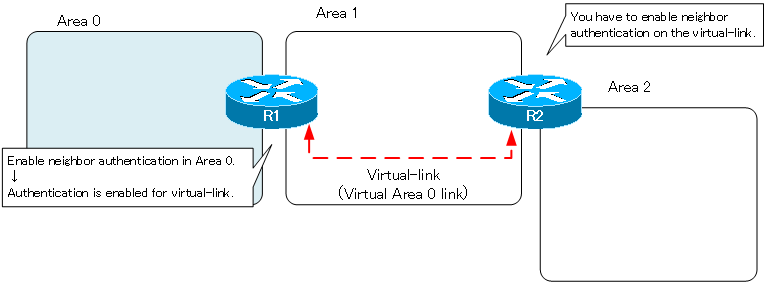
You have to be very careful when enabling neighbor authentication in area 0 when a virtual-link exists. A virtual-link is a virtual area 0 link. When neighbor authentication is enabled in area 0, neighbor authentication is also enabled on the virtual-link. Therefore, neighbor authentication must also be enabled on routers at the endpoints of the virtual-link that are not physically connected to Area 0.
Neighbor authentication and virtual-link configuration example
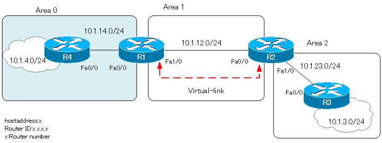
Consider the following network diagram for virtual-link and neighbor authentication.
Configuration file download
Related article
The following article explains in detail the configuration commands for OSPF neighbor authentication on Cisco routers.
Before enabling neighbor authentication
A virtual link is configured between R1 and R2 so that area 2 is virtually adjacent to the backbone area.
R1
router ospf 1
 router-id 1.1.1.1
 area 1 virtual-link 2.2.2.2
R2
router ospf 1
 router-id 2.2.2.2
 area 1 virtual-link 1.1.1.1
The show ip ospf virtual-links command clearly shows that the virtual-link has been established successfully.
R1#show ip ospf virtual-links
Virtual Link OSPF_VL0 to router 2.2.2.2 is up
  Run as demand circuit
  DoNotAge LSA allowed.
  Transit area 1, via interface FastEthernet1/0, Cost of using 1
  Transmit Delay is 1 sec, State POINT_TO_POINT,
  Timer intervals configured, Hello 10, Dead 40, Wait 40, Retransmit 5
    Hello due in 00:00:02
    Adjacency State FULL (Hello suppressed)
    Index 1/2, retransmission queue length 0, number of retransmission 1
    First 0x0(0)/0x0(0) Next 0x0(0)/0x0(0)
    Last retransmission scan length is 1, maximum is 1
    Last retransmission scan time is 0 msec, maximum is 0 msec
Since the virtual-link has been established successfully, communication between 10.1.4.0/24 in Area 0 and 10.1.3.0/24 in Area 2 is possible.
R4#show ip route ospf
     10.0.0.0/24 is subnetted, 5 subnets
O IA    10.1.12.0 [110/2] via 10.1.14.1, 00:09:00, FastEthernet0/0
O IA    10.1.3.0 [110/4] via 10.1.14.1, 00:09:00, FastEthernet0/0
O IA    10.1.23.0 [110/3] via 10.1.14.1, 00:09:00, FastEthernet0/0
R4#ping 10.1.3.3 source 10.1.4.4

Type escape sequence to abort.
Sending 5, 100-byte ICMP Echos to 10.1.3.3, timeout is 2 seconds:
Packet sent with a source address of 10.1.4.4
!!!!!
Success rate is 100 percent (5/5), round-trip min/avg/max = 60/88/112 ms----
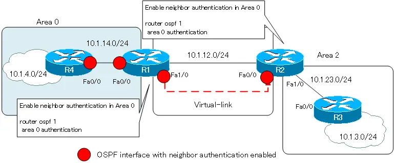
Enable neighbor authentication in area 0.
Enable neighbor authentication on R1 and R4 in area 0. To simplify the configuration, enable plaintext password authentication and use the password “cisco”.
R1/R4
interface FastEthernet0/0
 ip ospf authentication-key cisco
!
router ospf 1
 area 0 authentication
After enabling neighbor authentication, verify the show ip ospf virtual-links command on R1.
R1
R1#show ip ospf virtual-links
Virtual Link OSPF_VL0 to router 2.2.2.2 is up
  Run as demand circuit
  DoNotAge LSA allowed.
  Transit area 1, via interface FastEthernet1/0, Cost of using 1
  Transmit Delay is 1 sec, State POINT_TO_POINT,
  Timer intervals configured, Hello 10, Dead 40, Wait 40, Retransmit 5
    Hello due in 00:00:04
  Simple password authentication enabled
OSPF_VL0, the virtual interface of the virtual-link, is up/up, but we have not been able to establish an adjacency on the virtual-link. We can also see that plaintext password authentication has been enabled on OSPF_VL0. As mentioned in the introduction, enabling neighbor authentication in area 0 will also enable authentication on the virtual-link.
Also verify the show ip ospf virtual-links command on R2, which is the opposite of R1 for virtual-link.
R2
R2#show ip ospf virtual-links
Virtual Link OSPF_VL0 to router 1.1.1.1 is up
  Run as demand circuit
  DoNotAge LSA allowed.
  Transit area 1, via interface FastEthernet0/0, Cost of using 1
  Transmit Delay is 1 sec, State POINT_TO_POINT,
  Timer intervals configured, Hello 10, Dead 40, Wait 40, Retransmit 5
    Hello due in 00:00:00
Neighbor authentication is not enabled on R2’s OSPF_VL0; the settings for neighbor authentication on the virtual-link of R1 and R2 do not match, and the virtual-link is not functioning. As a result, communication between Area 0 and Area 2 is not possible.
R4
R4#show ip route ospf
     10.0.0.0/24 is subnetted, 3 subnets
O IA    10.1.12.0 [110/2] via 10.1.14.1, 00:06:03, FastEthernet0/0
R4#ping 10.1.3.3 source 10.1.4.4

Type escape sequence to abort.
Sending 5, 100-byte ICMP Echos to 10.1.3.3, timeout is 2 seconds:
Packet sent with a source address of 10.1.4.4
.....
Success rate is 0 percent (0/5)
Once you have enabled neighbor authentication in Area 0, you must also enable authentication on the endpoint router of virtual-link that is not physically connected to Area 0.

Enable neighbor authentication on virtual-link.
Enable neighbor authentication on R2, which is the endpoint of the virtual link that is not physically connected to area 0. The authentication password is configured as “cisco”. The authentication password is also configured on R1.
R1
router ospf 1
 area 1 virtual-link 2.2.2.2 authentication-key cisco
R2
router ospf 1
 area 0 authentication
 area 1 virtual-link 1.1.1.1 authentication-key cisco
If neighbor authentication on virtual-link is configured correctly, the show ip ospf virtual-links command will look like this
R1
R1#show ip ospf virtual-links
Virtual Link OSPF_VL0 to router 2.2.2.2 is up
  Run as demand circuit
  DoNotAge LSA allowed.
  Transit area 1, via interface FastEthernet1/0, Cost of using 1
  Transmit Delay is 1 sec, State POINT_TO_POINT,
  Timer intervals configured, Hello 10, Dead 40, Wait 40, Retransmit 5
    Hello due in 00:00:01
    Adjacency State FULL (Hello suppressed)
    Index 1/2, retransmission queue length 0, number of retransmission 0
    First 0x0(0)/0x0(0) Next 0x0(0)/0x0(0)
    Last retransmission scan length is 0, maximum is 0
    Last retransmission scan time is 0 msec, maximum is 0 msec
  Simple password authentication enabled
R2
R2#show ip ospf virtual-links
Virtual Link OSPF_VL0 to router 1.1.1.1 is up
  Run as demand circuit
  DoNotAge LSA allowed.
  Transit area 1, via interface FastEthernet0/0, Cost of using 1
  Transmit Delay is 1 sec, State POINT_TO_POINT,
  Timer intervals configured, Hello 10, Dead 40, Wait 40, Retransmit 5
    Hello due in 00:00:02
    Adjacency State FULL (Hello suppressed)
    Index 1/2, retransmission queue length 0, number of retransmission 0
    First 0x0(0)/0x0(0) Next 0x0(0)/0x0(0)
    Last retransmission scan length is 0, maximum is 0
    Last retransmission scan time is 0 msec, maximum is 0 msec
  Simple password authentication enabled
If the virtual-link has been established successfully, communication between Area 0 and Area 2 is possible.
R4#show ip route ospf
     10.0.0.0/24 is subnetted, 5 subnets
O IA    10.1.12.0 [110/2] via 10.1.14.1, 00:09:00, FastEthernet0/0
O IA    10.1.3.0 [110/4] via 10.1.14.1, 00:09:00, FastEthernet0/0
O IA    10.1.23.0 [110/3] via 10.1.14.1, 00:09:00, FastEthernet0/0
R4#ping 10.1.3.3 source 10.1.4.4

Type escape sequence to abort.
Sending 5, 100-byte ICMP Echos to 10.1.3.3, timeout is 2 seconds:
Packet sent with a source address of 10.1.4.4
!!!!!
Success rate is 100 percent (5/5), round-trip min/avg/max = 60/88/112 ms
How the OSPF works
- OSPF Overview
- OSPF process flow
- OSPF Router ID : Identify OSPF routers
- What if the router ID of the OSPF router is duplicated?
- OSPF Neighbor and Adjacency
- OSPF DR/BDR
- How show ip ospf neighbor looks on Ethernet
- OSPF Network Type : Classification of OSPF-enabled interfaces
- Synchronization process of OSPF LSDB
- Problems with large-scale OSPF network
- OSPF Area – Inside the area, in detail; outside the area, just a summary
- OSPF Router Type
- OSPF LSA Type
- OSPF Area Type
- OSPF Basic Configuration and Verification Commands
- Details of enabling OSPF on the interface
- OSPF Advertising Loopback Interface
- Configuring and Verifying OSPF Hello/Dead interval
- OSPF Cost Configuration and Verification
- Configuring and Verifying OSPF Router Priority
- Configuring OSPF Neighbor Authentication
- Neighbor Authentication over Virtual-link
- OSPF Configuring and Verifying Stub area [Cisco]
- OSPF Stub Area Configuration Example [Cisco]
- OSPF default route generation : default-information originate command
- Configuration Example of OSPF default route generation : stub area
- OSPF Virtual-Link : Virtual area 0 point-to-point link
- Configuring and Verifying OSPF Virtual-link [Cisco]
- OSPF Virtual-link Configuration Example [Cisco]
- OSPF Virtual-link for discontinuous backbone configuration example
- OSPF Route Summary and Configuration
- Cisco OSPF Route Summary Configuration Example
- OSPF Route Type Preference
- Why the OSPF neighbor state gets stuck in Exstart?
- OSPF packet type and header format
- OSPF Hello Packet
- OSPF DD(Database Description) Packet
- OSPF LSR(Link State Request) Packet
- OSPF LSU(Link State Update) Packet
- OSPF LSAck(Link State Acknowledgement) Packet
- Limitation of OSPF redistribution routes – redistribute maximum-prefix command
- Overview of LSA Filters for OSPF – Filter LSA Type 3/Type 5
- Configuration example of LSA type 3 filter
- Configuration example of LSA type 5 filter
- OSPFv3 Configuration Example [Cisco]
- Configuration Example of OSPFv3 Route Summary [Cisco]