
Table of Contents
Adjacent to DR/BDR
In a multi-access network such as Ethernet, the DR/BDR is elected. Then, synchronize the DR/BDR with the LSDB. Configure OSPF on the four Cisco routers on the Ethernet and make sure that they are only adjacent to the DR.
Related article
See the following articles on neighbor and adjacency and DR/BDR.
Network Topology
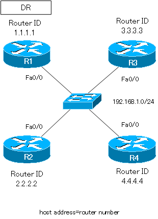
Make sure that R1 is the DR. For the sake of simplicity, we will not elect a BDR; we will set the router priority to 0 on R2 to R4.
Configuration
The OSPF-related configuration for each router is as follows
R1
interface FastEthernet0/0
 ip address 192.168.1.1 255.255.255.0
 ip ospf priority 100
!
router ospf 1
 router-id 1.1.1.1
 log-adjacency-changes
 network 192.168.1.1 0.0.0.0 area 0
R2
interface FastEthernet0/0
 ip address 192.168.1.2 255.255.255.0
 ip ospf priority 0
!
router ospf 1
 router-id 2.2.2.2
 log-adjacency-changes
 network 192.168.1.2 0.0.0.0 area 0
R3
interface FastEthernet0/0
 ip address 192.168.1.3 255.255.255.0
 ip ospf priority 0
!
router ospf 1
 router-id 3.3.3.3
 log-adjacency-changes
 network 192.168.1.3 0.0.0.0 area 0
R4
interface FastEthernet0/0
 ip address 192.168.1.4 255.255.255.0
 ip ospf priority 0
!
router ospf 1
 router-id 4.4.4.4
 log-adjacency-changes
 network 192.168.1.4 0.0.0.0 area 0
Display of show ip ospf neighbor
R1
Display show ip ospf neighbor on R1, which is the DR.
R1 show ip ospf neighbor
R1#show ip ospf neighbor


Neighbor ID     Pri   State           Dead Time   Address         Interface
3.3.3.3           0   FULL/DROTHER    00:00:39    192.168.1.3     FastEthernet0/0
2.2.2.2           0   FULL/DROTHER    00:00:39    192.168.1.2     FastEthernet0/0
4.4.4.4           0   FULL/DROTHER    00:00:39    192.168.1.4     FastEthernet0/0
We can see that R1 has established adjacency with R2, R3, and F4, and is in FULL state; FULL state is the state of LSDB synchronization.
R2
R2 show ip ospf neighbor
R2#show ip ospf neighbor


Neighbor ID     Pri   State           Dead Time   Address         Interface
4.4.4.4           0   2WAY/DROTHER    00:00:39    192.168.1.4     FastEthernet0/0
1.1.1.1         100   FULL/DR         00:00:39    192.168.1.1     FastEthernet0/0
3.3.3.3           0   2WAY/DROTHER    00:00:39    192.168.1.3     FastEthernet0/0
If you look at the show ip ospf neighbor on R2, you will see that it has established an adjacency only with R1, which is the DR, and is in the FULL state, while it is in the 2-way state with R3 and R4, which are just neighbors.
R3
R3 show ip ospf neighbor
R3#show ip ospf neighbor


Neighbor ID     Pri   State           Dead Time   Address         Interface
2.2.2.2           0   2WAY/DROTHER    00:00:39    192.168.1.2     FastEthernet0/0
4.4.4.4           0   2WAY/DROTHER    00:00:39    192.168.1.4     FastEthernet0/0
1.1.1.1         100   FULL/DR         00:00:39    192.168.1.1     FastEthernet0/0
On R3, it is the same as R2; it is in FULL state, having established adjacency with R1, the DR.
R4
R4 show ip ospf neighbor
R4#show ip ospf neighbor


Neighbor ID     Pri   State           Dead Time   Address         Interface
3.3.3.3           0   2WAY/DROTHER    00:00:31    192.168.1.3     FastEthernet0/0
2.2.2.2           0   2WAY/DROTHER    00:00:31    192.168.1.2     FastEthernet0/0
1.1.1.1         100   FULL/DR         00:00:31    192.168.1.1     FastEthernet0/0
R4 is the same as R2 and R3; it has established adjacency with R1, the DR, and is in the FULL state.
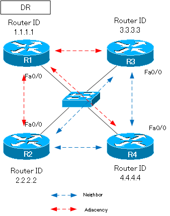
Summary of neighbor and adjacency
This section summarizes the relationship between routers R1 to R4.
| Relationship | Between Routers |
| neighbor(2WAY) | R2-R3,R2-R4,R3-R4 |
| adjacency(FULL) | R1-R2,R1-R3,R1-R4 |
How the OSPF works
- OSPF Overview
- OSPF process flow
- OSPF Router ID : Identify OSPF routers
- What if the router ID of the OSPF router is duplicated?
- OSPF Neighbor and Adjacency
- OSPF DR/BDR
- How show ip ospf neighbor looks on Ethernet
- OSPF Network Type : Classification of OSPF-enabled interfaces
- Synchronization process of OSPF LSDB
- Problems with large-scale OSPF network
- OSPF Area – Inside the area, in detail; outside the area, just a summary
- OSPF Router Type
- OSPF LSA Type
- OSPF Area Type
- OSPF Basic Configuration and Verification Commands
- Details of enabling OSPF on the interface
- OSPF Advertising Loopback Interface
- Configuring and Verifying OSPF Hello/Dead interval
- OSPF Cost Configuration and Verification
- Configuring and Verifying OSPF Router Priority
- Configuring OSPF Neighbor Authentication
- Neighbor Authentication over Virtual-link
- OSPF Configuring and Verifying Stub area [Cisco]
- OSPF Stub Area Configuration Example [Cisco]
- OSPF default route generation : default-information originate command
- Configuration Example of OSPF default route generation : stub area
- OSPF Virtual-Link : Virtual area 0 point-to-point link
- Configuring and Verifying OSPF Virtual-link [Cisco]
- OSPF Virtual-link Configuration Example [Cisco]
- OSPF Virtual-link for discontinuous backbone configuration example
- OSPF Route Summary and Configuration
- Cisco OSPF Route Summary Configuration Example
- OSPF Route Type Preference
- Why the OSPF neighbor state gets stuck in Exstart?
- OSPF packet type and header format
- OSPF Hello Packet
- OSPF DD(Database Description) Packet
- OSPF LSR(Link State Request) Packet
- OSPF LSU(Link State Update) Packet
- OSPF LSAck(Link State Acknowledgement) Packet
- Limitation of OSPF redistribution routes – redistribute maximum-prefix command
- Overview of LSA Filters for OSPF – Filter LSA Type 3/Type 5
- Configuration example of LSA type 3 filter
- Configuration example of LSA type 5 filter
- OSPFv3 Configuration Example [Cisco]
- Configuration Example of OSPFv3 Route Summary [Cisco]