Table of Contents
Overview
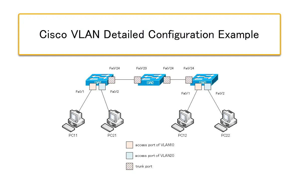
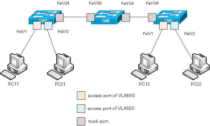
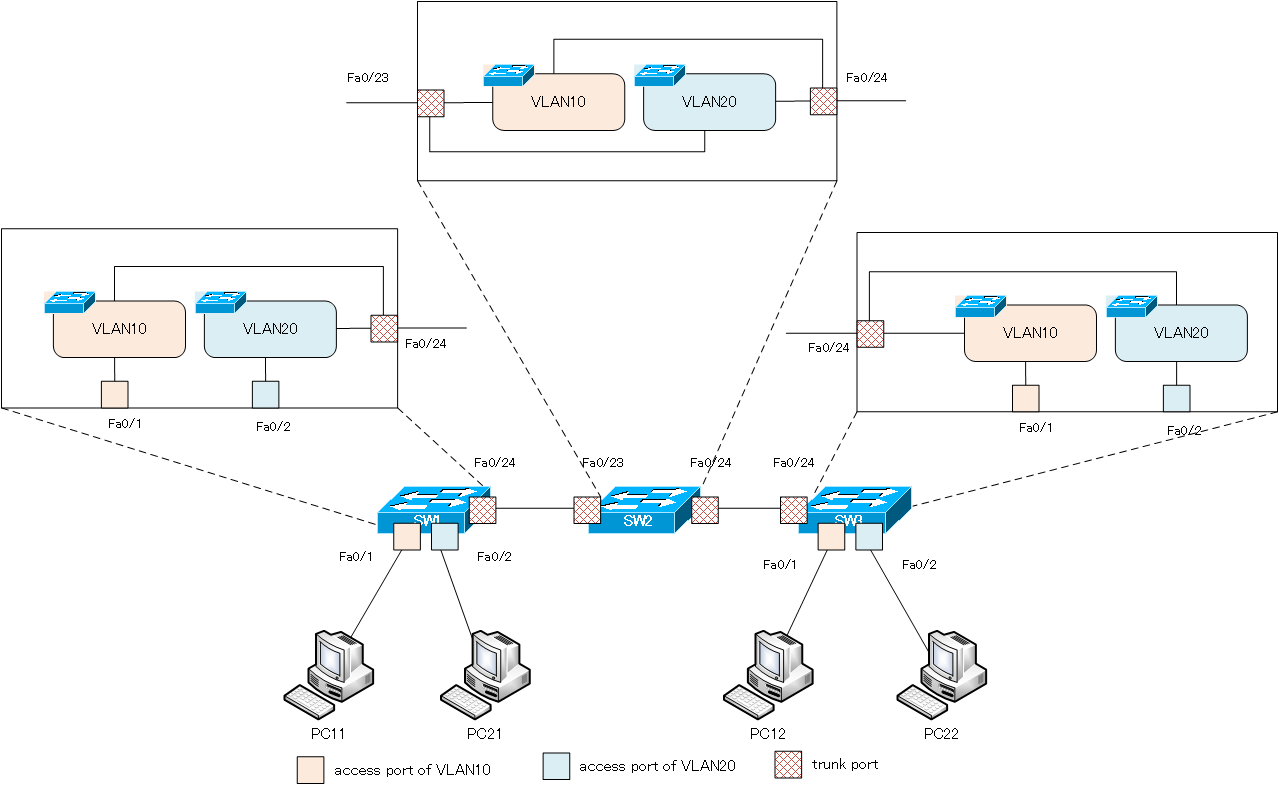
We will configure two independent networks using VLANs on three switches, SW1/SW2/SW3. To do so, we will create VLANs and configure access ports/trunk ports (tag VLANs). When configuring VLANs, make sure you have a clear picture of how the VLANs and ports will be associated inside the switch.
Related article
For more information about VLAN configuration and verification commands, please refer to the following article.
Download
You can download the file for Cisco Packet Tracer about the configuration example on this page.
Network Diagram
| PC | IP address |
|---|---|
| PC11 | 192.168.10.11/24 |
| PC12 | 192.168.10.12/24 |
| PC21 | 192.168.20.21/24 |
| PC22 | 192.168.20.22/24 |
Configuration Condition
- Create VLAN10 and VLAN20 on SW1/SW2/SW3.
- Configure the port to which the PC is connected as the access port for the appropriate VLAN.
- Configure the port of the link between the switches as a trunk port.
- Verify that communication is possible between PC11 and PC12 in VLAN 10 and between PC21 and PC22 in VLAN 20.
Initial Configuration
SW1/SW2/SW3
- Hostname
PC11/PC12/PC21/PC22
- Hostname
- IP address/subnetmask
Configuration and Verification
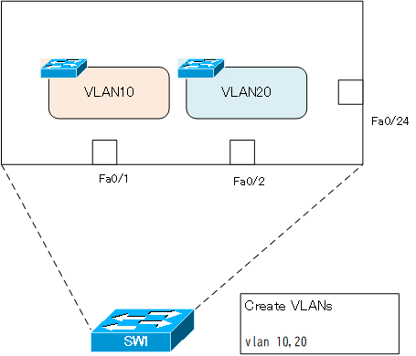
Step1: Create VLANs
Create VLAN10 and VLAN20 on SW1/SW2/SW3. VLAN10 and VLAN20 are required not only for SW1 and SW3, but also for SW2.
SW1/SW2/SW3
vlan 10,20
Just creating a VLAN is just creating a virtual switch that does not have any ports inside the switch; if you create VLAN10 and VLAN20 in SW1, it will look like the following figure.
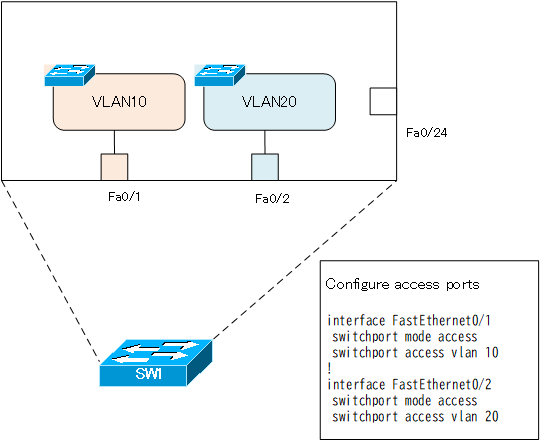
Step2: Configure access ports
Assign ports to the VLANs created in Step 1, and configure the access ports for VLAN10 and VLAN20 on SW1 and SW3. Configuring an access port means having a port on a virtual switch for each VLAN inside the switch.
| Switch | Port | VLAN | connected to |
|---|---|---|---|
| SW1 | Fa0/1 | 10 | PC11 |
| Fa0/2 | 20 | PC21 | |
| SW3 | Fa0/1 | 10 | PC12 |
| Fa0/2 | 20 | PC22 |
In this network diagram, the commands are the same for both SW1 and SW3 for the access port configuration.
SW1/SW3
interface FastEthernet0/1
 switchport mode access
 switchport access vlan 10
!
interface FastEthernet0/2
 switchport mode access
 switchport access vlan 20
Step3: Verify the VLAN and access port.
Verify that the VLAN and access port assignments are configured correctly by using the show vlan brief command on SW1 and SW3. the output on SW1 is as follows
SW1
SW1#show vlan brief

VLAN Name                             Status    Ports
---- -------------------------------- --------- -------------------------------
1    default                          active    Fa0/3, Fa0/4, Fa0/5, Fa0/6
                                                Fa0/7, Fa0/8, Fa0/9, Fa0/10
                                                Fa0/11, Fa0/12, Fa0/13, Fa0/14
                                                Fa0/15, Fa0/16, Fa0/17, Fa0/18
                                                Fa0/19, Fa0/20, Fa0/21, Fa0/22
                                                Fa0/23, Fa0/24, Gig0/1, Gig0/2
10   VLAN0010                         active    Fa0/1
20   VLAN0020                         active    Fa0/2
1002 fddi-default                     active
1003 token-ring-default               active
1004 fddinet-default                  active
1005 trnet-default                    active
By configuring the access port, a virtual switch inside the switch by VLAN can have a port. the internal VLAN and port assignment in SW1 is as follows.
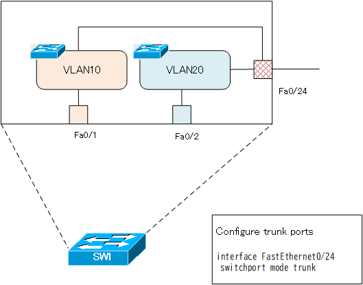
Step4: Configure trunk ports.
Ethernet frames for VLAN 10 and VLAN 20 must be forwarded between each switch on a single link. Configure a trunk (tag VLAN) port to forward Ethernet frames of multiple VLANs on a single link.
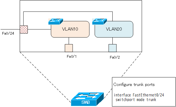
SW1/SW3
interface FastEthernet0/24
 switchport mode trunk
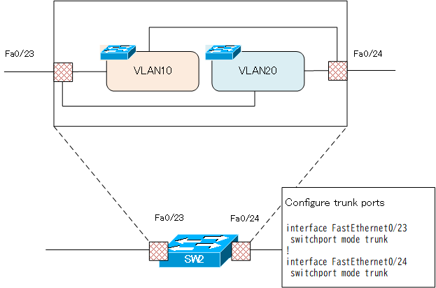
SW2
interface FastEthernet0/23
 switchport mode trunk
!
interface FastEthernet0/24
 switchport mode trunk
Step5: Verify trunk ports
Verify that the ports between each switch are properly operating as trunk ports. It is easy to understand using the show interface trunk command; for SW1, the display is as follows
SW1
SW1#show interfaces trunk
Port        Mode         Encapsulation  Status        Native vlan
Fa0/24      on           802.1q         trunking      1

Port        Vlans allowed on trunk
Fa0/24      1-1005

Port        Vlans allowed and active in management domain
Fa0/24      1,10,20

Port        Vlans in spanning tree forwarding state and not pruned
Fa0/24      1,10,20
Trunk port is assigned to multiple VLANs, so SW1 Fa0/24 is assigned to both VLAN10 and VLAN20.
The display of the show interface trunk command on SW2 is as follows
SW2
SW2#show interfaces trunk
Port        Mode         Encapsulation  Status        Native vlan
Fa0/23      on           802.1q         trunking      1
Fa0/24      on           802.1q         trunking      1

Port        Vlans allowed on trunk
Fa0/23      1-1005
Fa0/24      1-1005

Port        Vlans allowed and active in management domain
Fa0/23      1,10,20
Fa0/24      1,10,20

Port        Vlans in spanning tree forwarding state and not pruned
Fa0/23      1,10,20
Fa0/24      1,10,20
The following figure shows the internal VLAN and port assignments of SW2.
The display of the show interface trunk command on SW3 is as follows
SW3
SW#show interfaces trunk
Port        Mode         Encapsulation  Status        Native vlan
Fa0/24      on           802.1q         trunking      1

Port        Vlans allowed on trunk
Fa0/24      1-1005

Port        Vlans allowed and active in management domain
Fa0/24      1,10,20

Port        Vlans in spanning tree forwarding state and not pruned
Fa0/24      1,10,20
And inside SW3, the correspondence between VLAN and port is as shown in the following figure.
The configuration of VLAN10 and VLAN20 across SW1/SW2/SW3 is now complete.
Step6: Verification of communication
Verify that communication within VLAN 10 and VLAN 20 across SW1/SW2/SW3 is successful. Pinging from PC11 to PC12 on VLAN10 returns a successful response.
PC11
C:\>ping 192.168.10.12

Pinging 192.168.10.12 with 32 bytes of data:

Reply from 192.168.10.12: bytes=32 time<1ms TTL=128
Reply from 192.168.10.12: bytes=32 time<1ms TTL=128
Reply from 192.168.10.12: bytes=32 time<1ms TTL=128
Reply from 192.168.10.12: bytes=32 time<1ms TTL=128

Ping statistics for 192.168.10.12:
    Packets: Sent = 4, Received = 4, Lost = 0 (0% loss),
Approximate round trip times in milli-seconds:
    Minimum = 0ms, Maximum = 0ms, Average = 0ms
In the same way, a ping from PC21 to PC22 on VLAN20 returns a successful response.
PC21
C:\>ping 192.168.20.22

Pinging 192.168.20.22 with 32 bytes of data:

Reply from 192.168.20.22: bytes=32 time<1ms TTL=128
Reply from 192.168.20.22: bytes=32 time<1ms TTL=128
Reply from 192.168.20.22: bytes=32 time<1ms TTL=128
Reply from 192.168.20.22: bytes=32 time<1ms TTL=128

Ping statistics for 192.168.20.22:
    Packets: Sent = 4, Received = 4, Lost = 0 (0% loss),
Approximate round trip times in milli-seconds:
    Minimum = 0ms, Maximum = 0ms, Average = 0ms
Step7: Consider logical topology
Consider the logical topology of the network that we have set up so far. Logical topology is an abstraction of the physical layout and wiring. The logical topology is how many networks there are and how each network is interconnected.
The internal VLANs and port assignments of SW1 to SW3 can be summarized again as shown in the following figure.
Rewrite the diagram a bit, paying attention to how the virtual switches of VLAN10 and VLAN20 created by the VLAN configuration in each switch are connected to each other.
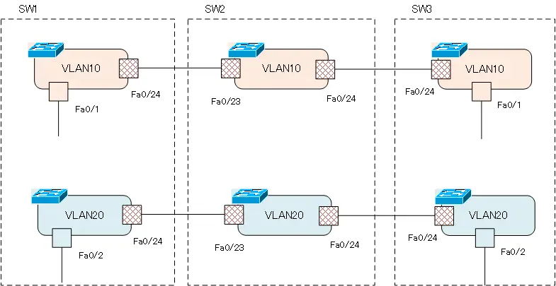
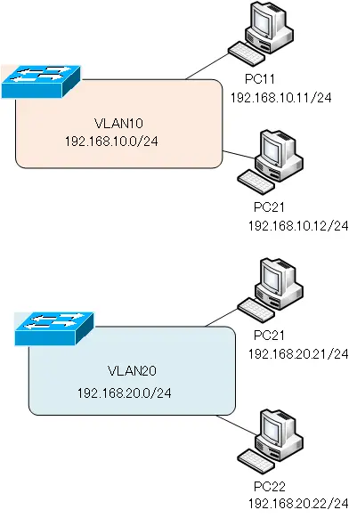
Then abstract from this. Let’s take away the frame of each switch. Also, don’t care about the physical wiring and ports anymore. We will merge VLAN10 and VLAN20, which are spread across each switch, into one. You will then have two independent VLAN10 networks and a VLAN20 network. Then, PC11 and PC12 are connected to the network of VLAN10, and PC21 and PC22 are connected to the network of VLAN20.
A VLAN is a single network, and TCP/IP identifies a network by its network address. In this network diagram, VLAN 10 is mapped to 192.168.10.0/24. Therefore, PC11 and PC12, which are connected to VLAN10, are configured with IP addresses in 192.168.10.0/24. VLAN 20 is mapped to 192.168.20.0/24. PC21 and PC22, which are connected to VLAN 20, are configured with IP addresses in 192.168.20.0/24.
Since VLAN10 and VLAN20 are independent, they cannot communicate with each other; if you need to communicate between VLAN10 and VLAN20, use inter-VLAN routing to interconnect the VLANs using a Layer 3 switch.
VLAN(Virtual LAN)
- The need to divide the network
- Details of dividing the network
- VLAN Overview
- VLAN behavior
- Access port : Port assigned to only one VLAN
- Trunk port : Port assigned to multiple VLANs
- Summary of Trunk Protocols – IEEE802.1Q and ISL
- Native VLAN
- Specific example of native VLAN mismatch
- Cisco DTP
- Cisco Configuring and Verifying VLAN
- Cisco VLAN Detailed Configuration Example
- Notes on deleting VLANs
- Voice VLAN – VLAN for connecting IP phones
- VTP :Synchronize VLAN configuration
- VTP pruning – Stopping unnecessary flooding of trunk links
- Configuring and Verifying Cisco VTP
- Inter VLAN routing overview
- Inter-VLAN routing by router
- Inter-VLAN routing by Layer 3 switch
- Configuring and Verifying Inter-VLAN Routing by Cisco Router
- Cisco Configuring Inter-VLAN routing by Layer3 switch : SVI/routed port
- Cisco Layer3 Switch Basic Configuration Example
- Summary of Layer 3 Switch Port Concepts – Access Port/Trunk Port/SVI/Routed Port
- LAN Design pattern : 2-tier and 3-tier