PPPoFRの設定
目次
ネットワーク構成
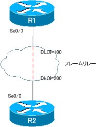
図 PPPoFRの設定 ネットワーク構成
設定条件
- R1-R2間で認証を行います。認証はパスワードを直接送信しない方式を利用します。認証に利用するユーザIDはルータのホスト名を利用し、パスワード「cisco」とします。
- R1-R2間のネットワークアドレスは192.168.12.0/24とします。ホストアドレスは、ルータ番号を利用します。
初期設定
- R1/R2
ホスト名 - フレームリレー
R1-R2間のPVC
※GNS3プロジェクトダウンロード(MM_1248_PPPoFR_init.zip)
設定と確認
【Step1:PPP over FRの設定】
フレームリレーには認証機能が備わっていません。フレームリレー上で認証を行うために、PPPoFRの設定を行います。PPPoFRの設定の手順は、次の通りです。
- Virtual Templateの設定
- PPP over FRのテンプレートを作成。Virtual TemplateにIPアドレスを設定する
- (config)#interface virtual-template
(config-if)#ip addressまたは
(config-if)#ip unnumbered - 認証の有効化もVirtual Templateで行う
(config-if)#ppp authentciation {chap|pap}
- Virtual Templeteをフレームリレーのインタフェースに適用
- (config-if)#frame-relay interface-dlci
ppp virtual-template - 1つのVirtual Templateを複数のポイントツーポイントサブインタフェースに適用可能
- (config-if)#frame-relay interface-dlci
R1
---------------------------------------------------------------------------------
username R2 password 0 cisco
!
interface Serial0/0
encapsulation frame-relay
no shutdown
!
interface Serial0/0.1 point-to-point
frame-relay interface-dlci 100 ppp Virtual-Template1
!
interface Virtual-Template1
ppp authentication chap
---------------------------------------------------------------------------------
R2
---------------------------------------------------------------------------------
username R1 password 0 cisco
!
interface Serial0/0
encapsulation frame-relay
no shutdown
!
interface Serial0/0.1 point-to-point
frame-relay interface-dlci 200 ppp Virtual-Template1
!
interface Virtual-Template1
ppp authentication chap
---------------------------------------------------------------------------------
【Step2:IPアドレスの設定】
PPPoFRのインタフェースにIPアドレスを設定するときには、Virtual-Template上で行います。
R1
---------------------------------------------------------------------------------
interface Virtual-Template1
ip address 192.168.12.1 255.255.255.0
---------------------------------------------------------------------------------
R2
---------------------------------------------------------------------------------
interface Virtual-Template1
ip address 192.168.12.2 255.255.255.0
---------------------------------------------------------------------------------
【Step3:PPPoFRの確認】
PPPoFRのインタフェースは、Virtual TempleteからVirtual Accessとして生成されます。R1のPPPoFRのVirtual Accessの状態は次のようになっています。
R1
---------------------------------------------------------------------------------
R1#show ip interface virtual-access 2
Virtual-Access2 is up, line protocol is up
Internet address is 192.168.12.1/24
Broadcast address is 255.255.255.255
Address determined by configuration file
Peer address is 192.168.12.2
MTU is 1500 bytes
Helper address is not set
Directed broadcast forwarding is disabled
Outgoing access list is not set
Inbound  access list is not set
Proxy ARP is enabled
Local Proxy ARP is disabled
Security level is default
Split horizon is enabled
ICMP redirects are always sent
ICMP unreachables are always sent
ICMP mask replies are never sent
IP fast switching is enabled
IP fast switching on the same interface is enabled
IP Flow switching is disabled
IP CEF switching is enabled
IP CEF Fast switching turbo vector
IP multicast fast switching is enabled
IP multicast distributed fast switching is disabled
IP route-cache flags are Fast, CEF
Router Discovery is disabled
IP output packet accounting is disabled
IP access violation accounting is disabled
TCP/IP header compression is disabled
RTP/IP header compression is disabled
Policy routing is disabled
Network address translation is disabled
BGP Policy Mapping is disabled
WCCP Redirect outbound is disabled
WCCP Redirect inbound is disabled
WCCP Redirect exclude is disabled
---------------------------------------------------------------------------------
そして、Virual-access2のインタフェースがup/upの状態なので、ルーティングテーブルにDirectly Connectedのルートで設定したIPアドレスに対応するネットワークアドレスが登録されています。また、PPPのインタフェースでもあるので対向のIPアドレス192.168.12.2の/32のホストルートも登録されています。
R1
---------------------------------------------------------------------------------
R1#show ip route
Codes: C - connected, S - static, R - RIP, M - mobile, B - BGP
D - EIGRP, EX - EIGRP external, O - OSPF, IA - OSPF inter area
N1 - OSPF NSSA external type 1, N2 - OSPF NSSA external type 2
E1 - OSPF external type 1, E2 - OSPF external type 2
i - IS-IS, su - IS-IS summary, L1 - IS-IS level-1, L2 - IS-IS level-2
ia - IS-IS inter area, * - candidate default, U - per-user static route
o - ODR, P - periodic downloaded static route
Gateway of last resort is not set
192.168.12.0/24 is variably subnetted, 2 subnets, 2 masks
C       192.168.12.0/24 is directly connected, Virtual-Access2
C       192.168.12.2/32 is directly connected, Virtual-Access2
---------------------------------------------------------------------------------