CCIE R&S Configuration Part1 2.6 MPLS-VPN
2.6.MPLS-VPN
- R1、R4をPEルータとします。また、SW1、SW2はCEルータとします。MPLSバックボーンのBGP AS番号を300とします。BGPネイバーはLoopback0で確立します。
- VRF名は「VPN」とし、RDは「300:1」を利用します。
- PE-CE間のルーティングプロトコルはOSPFを利用します。
- サイト1からサイト2への通信はMPLS経由で行わるようにしてください。ただし、サイト1のR3からの通信は除きます。これを実現するために、R1、R4で新しく168.100.0/24の範囲からLoopbackインタフェースを作成してもかまいません。
【設定】
R1
---------------------------------------------------------------------------------
ip vrf VPN
 rd 300:1
 route-target export 300:1
 route-target import 300:1
!
interface Loopback100
 ip vrf forwarding VPN
 ip address 192.168.100.1 255.255.255.255
!
interface FastEthernet0/0
 ip vrf forwarding VPN
 ip address 192.168.0.130 255.255.255.224
!
interface FastEthernet1/0
 mpls ip
!
router ospf 1 vrf VPN
 router-id 1.1.1.1
 log-adjacency-changes
 auto-cost reference-bandwidth 3000
 area 0 sham-link 192.168.100.1 192.168.100.4
 area 16 virtual-link 6.6.6.6
 redistribute bgp 300 subnets
 network 192.168.0.130 0.0.0.0 area 16
!
router bgp 300
 no bgp default ipv4-unicast
 bgp log-neighbor-changes
 neighbor 192.168.4.4 remote-as 300
 neighbor 192.168.4.4 update-source Loopback0
!
 address-family vpnv4
  neighbor 192.168.4.4 activate
  neighbor 192.168.4.4 send-community extended
  neighbor 192.168.4.4 next-hop-self
 exit-address-family
!
 address-family ipv4 vrf VPN
  redistribute ospf 1 vrf VPN
  no synchronization
  network 192.168.100.1 mask 255.255.255.255
 exit-address-family
---------------------------------------------------------------------------------
R4
---------------------------------------------------------------------------------
ip vrf VPN
 rd 300:1
 route-target export 300:1
 route-target import 300:1
!
interface Loopback100
 ip vrf forwarding VPN
 ip address 192.168.100.4 255.255.255.255
!
interface FastEthernet0/0
 ip vrf forwarding VPN
 ip address 192.168.128.130 255.255.255.224
!
interface FastEthernet1/0
 mpls ip
!
router ospf 1 vrf VPN
 router-id 4.4.4.4
 log-adjacency-changes
 auto-cost reference-bandwidth 3000
 area 0 sham-link 192.168.100.4 192.168.100.1
 redistribute bgp 300 subnets
 network 192.168.128.130 0.0.0.0 area 1
!
router bgp 300
 no bgp default ipv4-unicast
 bgp log-neighbor-changes
 neighbor 192.168.1.1 remote-as 300
 neighbor 192.168.1.1 update-source Loopback0
!
 address-family vpnv4
  neighbor 192.168.1.1 activate
  neighbor 192.168.1.1 send-community extended
  neighbor 192.168.1.1 next-hop-self
 exit-address-family
!
 address-family ipv4 vrf VPN
  redistribute ospf 1 vrf VPN
  no synchronization
  network 192.168.100.4 mask 255.255.255.255
 exit-address-family
---------------------------------------------------------------------------------
SW1
---------------------------------------------------------------------------------
router ospf 1
 area 16 virtual-link 1.1.1.1
---------------------------------------------------------------------------------
【確認のポイント】
- show mpls ldp neighbor
R1-R4間でLDPネイバーを確立できていることを確認します。 - show ip bgp vpnv4 all
R1-R4でVPNv4ルートを交換できていることを確認します。 - show ip ospf sham-links
R1-R4間でSham-linkが正常に確立できていることを確認します。 - show ip route
R2のルーティングテーブル上でサイト2のルートがMPLS-VPN経由となっていることを確認します。
【解説】
MPLS-VPNでサイト1とサイト2を接続して、MPLS-VPN経由でサイト間の通信を行うことができるようにする問題です。PE-CE間にOSPFを利用しているときの、かなり深いレベルの知識がないと設定できない、非常に難しい問題です。
まず、基本的なMPLS-VPNの設定についてみていきます。
R1-R4がMPLS-VPNのバックボーンを構成します。そのため、R1、R4 F1/0でLDPを有効化して、ラベルスイッチングを行います。また、R1-R4間でMP-BGPネイバーを確立して、VPNv4ルートを交換できるようにします。そのための設定は次の部分です。
R1
---------------------------------------------------------------------------------
interface FastEthernet1/0
 mpls ip
!
router bgp 300
 no bgp default ipv4-unicast
 bgp log-neighbor-changes
 neighbor 192.168.4.4 remote-as 300
 neighbor 192.168.4.4 update-source Loopback0
!
 address-family vpnv4
  neighbor 192.168.4.4 activate
  neighbor 192.168.4.4 send-community extended
  neighbor 192.168.4.4 next-hop-self
 exit-address-family
---------------------------------------------------------------------------------
R4
---------------------------------------------------------------------------------
interface FastEthernet1/0
 mpls ip
!
router bgp 300
 no bgp default ipv4-unicast
 bgp log-neighbor-changes
 neighbor 192.168.1.1 remote-as 300
 neighbor 192.168.1.1 update-source Loopback0
!
 address-family vpnv4
  neighbor 192.168.1.1 activate
  neighbor 192.168.1.1 send-community extended
  neighbor 192.168.1.1 next-hop-self
 exit-address-family
---------------------------------------------------------------------------------
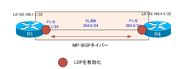
図 R1-R4noMPLS-VPNバックボーン
次に、PEルータとなるR1、R4でVRFを定義して各サイトのルートをVPNv4ルートとして扱えるようにします。そのための設定は、R1/R4の次の部分です。
R1
---------------------------------------------------------------------------------
ip vrf VPN
 rd 300:1
 route-target export 300:1
 route-target import 300:1
!
interface FastEthernet0/0
 ip vrf forwarding VPN
 ip address 192.168.0.130 255.255.255.224
!
router ospf 1 vrf VPN
 router-id 1.1.1.1
 log-adjacency-changes
 auto-cost reference-bandwidth 3000
 redistribute bgp 300 subnets
 network 192.168.0.130 0.0.0.0 area 16
!
router bgp 300
 no bgp default ipv4-unicast
 bgp log-neighbor-changes
 neighbor 192.168.4.4 remote-as 300
 neighbor 192.168.4.4 update-source Loopback0
!
 address-family ipv4 vrf VPN
  redistribute ospf 1 vrf VPN
  no synchronization
 exit-address-family
---------------------------------------------------------------------------------
R4
---------------------------------------------------------------------------------
ip vrf VPN
 rd 300:1
 route-target export 300:1
 route-target import 300:1
!
interface FastEthernet0/0
 ip vrf forwarding VPN
 ip address 192.168.128.130 255.255.255.224
!
router ospf 1 vrf VPN
 router-id 4.4.4.4
 log-adjacency-changes
 auto-cost reference-bandwidth 3000
 redistribute bgp 300 subnets
 network 192.168.128.130 0.0.0.0 area 1
!
router bgp 300
 no bgp default ipv4-unicast
 bgp log-neighbor-changes
 neighbor 192.168.1.1 remote-as 300
 neighbor 192.168.1.1 update-source Loopback0
!
 address-family ipv4 vrf VPN
  redistribute ospf 1 vrf VPN
  no synchronization
 exit-address-family
---------------------------------------------------------------------------------
PEルータとなるR1、R4ではVRF「VPN」のためのOSPFプロセスを新たに再設定しなければいけないことに注意してください。そして、VRFに割り当てるR1、R4 F0/0ではIPアドレスの再設定も必要です。
そして、サイト1のOSPFのエリア構成からVirtual Linkの設定が必要となります。MPLS-VPNバックボーンは、OSPFスーパーバックボーンとしてエリア0のように振る舞います。スーパーバックボーンとSW1、R2、R3のエリア0が分断されることになります。
スーパーバックボーンとエリア0を接続するために、R1とSW1でVirtual Linkを設定します。
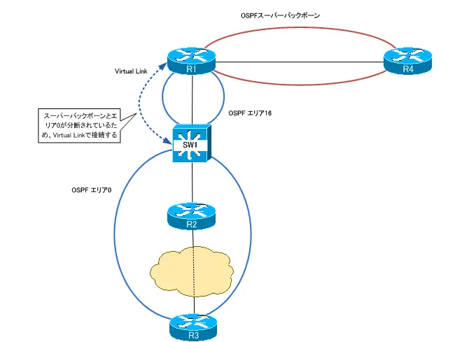
図 スーパーバックボーンとエリア0の接続
R1
---------------------------------------------------------------------------------
router ospf 1 vrf VPN
 area 16 virtual-link 6.6.6.6
---------------------------------------------------------------------------------
SW1
---------------------------------------------------------------------------------
router ospf 1
 area 16 virtual-link 1.1.1.1
---------------------------------------------------------------------------------
ただし、このままではサイト間の通信はMPLS-VPN経由ではなく、R3-R5のPPPリンクを経由します。MPLS-VPN経由、つまり、MP-BGPで学習したルートよりもOSPFで学習したルートの方が優先されるからです。
具体的にサイト2の192.168.128.160/27のルートについて考えます。192.168.128.160/27のルートは、R4でMP-BGPルートとしてR1へ送信されます。また、192.168.128.160/27のルートはPPPリンク経由でR1へ送信されます。R1ではサイト2の192.168.128.160/27のルートをMP-BGPとOSPFで学習します。MP-BGPのルートはIBGPルートなのでAD 200です。そのため、MPLS-VPN経由のMP-BGPルートよりもOSPFルートを優先します。
サイト間のルートはMPLS-VPN経由ではなく、PPPリンク経由でアドバタイズされることになります。サイト間のルートがPPPリンク経由なので、パケットのルーティング経路もPPPリンク経由となってしまいます。
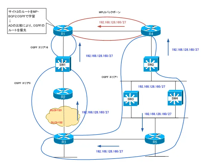
図 サイト間のルートのアドバタイズ
サイト間のルートがMPLS-VPN経由でアドバタイズされるようにするために、R1-R4間でSham-linkを設定して、MPLS-VPNをまたがったOSPFエリアを構成します。
R1、R4でのSham-linkの設定は次の通りです。
R1 Sham-link
---------------------------------------------------------------------------------
interface Loopback100
 ip vrf forwarding VPN
 ip address 192.168.100.1 255.255.255.255
!
router ospf 1 vrf VPN
 area 0 sham-link 192.168.100.1 192.168.100.4
!
router bgp 300
!
 address-family ipv4 vrf VPN
  network 192.168.100.1 mask 255.255.255.255
 exit-address-family
---------------------------------------------------------------------------------
R4
---------------------------------------------------------------------------------
interface Loopback100
 ip vrf forwarding VPN
 ip address 192.168.100.4 255.255.255.255
!
router ospf 1 vrf VPN
 area 0 sham-link 192.168.100.4 192.168.100.1
!
router bgp 300
!
 address-family ipv4 vrf VPN
  network 192.168.100.4 mask 255.255.255.255
 exit-address-family
---------------------------------------------------------------------------------
Sham-linkやVirtual-linkを考慮した実質的なOSPFエリア構成は次の図のようになります。
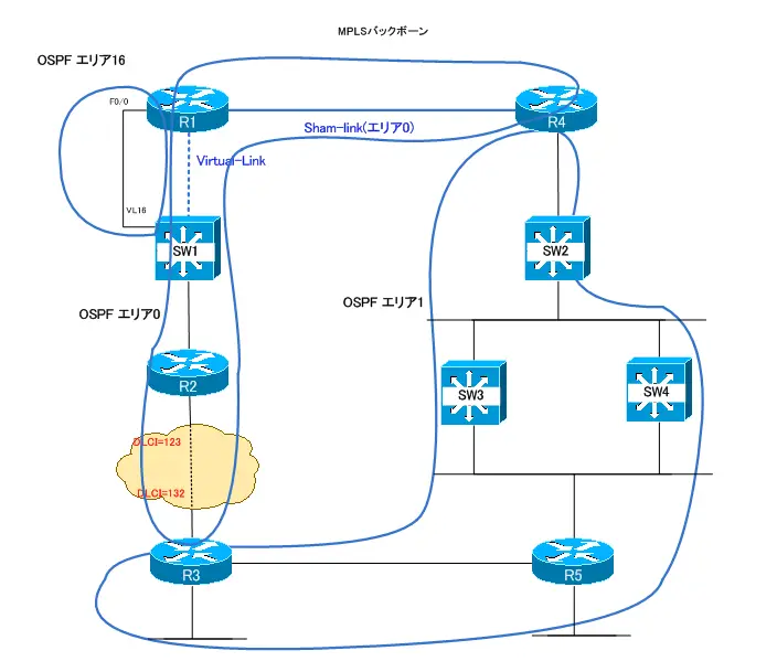
図 実質的なOSPFエリア構成
Sham-linkの設定を確認するには、show ip ospf sham-linksコマンドを利用します。R1では、次のような出力になっています。
R1 show ip ospf sham-link
---------------------------------------------------------------------------------
R1#show ip ospf sham-links
Sham Link OSPF_SL0 to address 192.168.100.4 is up
Area 0 source address 192.168.100.1
Run as demand circuit
DoNotAge LSA allowed. Cost of using 1 State POINT_TO_POINT,
Timer intervals configured, Hello 10, Dead 40, Wait 40,
Hello due in 00:00:03
Adjacency State FULL (Hello suppressed)
Index 2/3, retransmission queue length 0, number of retransmission 0
First 0x0(0)/0x0(0) Next 0x0(0)/0x0(0)
Last retransmission scan length is 0, maximum is 0
Last retransmission scan time is 0 msec, maximum is 0 msec
---------------------------------------------------------------------------------
Sham-linkを設定することによって、サイト間のルートがMPLS-VPN(Sham-link)経由でアドバタイズされるようになります。その結果、R2でルーティングテーブルを確認すると、サイト間のルートはMPLS-VPN経由となることがわかります。また、R2からサイト2のネットワークへTracerouteすると、MPLS-VPN経由でルーティングされていることがわかります。
R2 show ip route/traceroute
---------------------------------------------------------------------------------
R2#show ip route
~省略~

Gateway of last resort is 192.168.0.98 to network 0.0.0.0

192.168.8.0/32 is subnetted, 1 subnets
O IA    192.168.8.8 [110/122] via 192.168.0.98, 11:38:39, FastEthernet0/0.26
192.168.128.0/27 is subnetted, 4 subnets
O IA    192.168.128.224
[110/181] via 192.168.0.98, 11:38:39, FastEthernet0/0.26
O IA    192.168.128.192
[110/151] via 192.168.0.98, 11:38:39, FastEthernet0/0.26
O IA    192.168.128.160
[110/121] via 192.168.0.98, 11:38:39, FastEthernet0/0.26
O IA    192.168.128.128
[110/91] via 192.168.0.98, 11:38:39, FastEthernet0/0.26
192.168.9.0/32 is subnetted, 1 subnets
O IA    192.168.9.9 [110/122] via 192.168.0.98, 11:38:39, FastEthernet0/0.26
192.168.5.0/32 is subnetted, 1 subnets
O IA    192.168.5.5 [110/152] via 192.168.0.98, 11:38:40, FastEthernet0/0.26
192.168.6.0/32 is subnetted, 1 subnets
O       192.168.6.6 [110/31] via 192.168.0.98, 11:38:40, FastEthernet0/0.26
192.168.7.0/32 is subnetted, 1 subnets
O IA    192.168.7.7 [110/92] via 192.168.0.98, 11:38:40, FastEthernet0/0.26
192.168.0.0/27 is subnetted, 4 subnets
C       192.168.0.96 is directly connected, FastEthernet0/0.26
C       192.168.0.64 is directly connected, FastEthernet0/0.2
O IA    192.168.0.32 [110/60] via 192.168.3.3, 11:38:40, Virtual-Access1
O IA    192.168.0.128 [110/60] via 192.168.0.98, 11:38:40, FastEthernet0/0.26
192.168.2.0/32 is subnetted, 1 subnets
C       192.168.2.2 is directly connected, Loopback0
192.168.100.0/32 is subnetted, 2 subnets
O E2    192.168.100.4 [110/1] via 192.168.0.98, 11:38:40, FastEthernet0/0.26
O E2    192.168.100.1 [110/1] via 192.168.0.98, 11:38:40, FastEthernet0/0.26
192.168.3.0/32 is subnetted, 1 subnets
C       192.168.3.3 is directly connected, Virtual-Access1
O*E2 0.0.0.0/0 [110/1] via 192.168.0.98, 11:38:40, FastEthernet0/0.26
O E2 198.1.0.0/16 [110/20] via 192.168.0.98, 03:09:32, FastEthernet0/0.26
R2#traceroute 192.168.128.161

Type escape sequence to abort.
Tracing the route to 192.168.128.161

1 192.168.0.98 80 msec 68 msec 24 msec
2 192.168.0.130 64 msec 824 msec 124 msec
3 192.168.128.130 [MPLS: Label 20 Exp 0] 108 msec 60 msec 100 msec
4 192.168.128.129 124 msec *  516 msec
---------------------------------------------------------------------------------
