Table of Contents
Overview
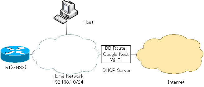
Connect the GNS3 Cisco router to the author’s home network and allow it to access the Internet.
Configuration Procedure
- Connecting R1 Fa0/0 on GNS3 to home network
- DHCP Client Configuration
- Verifying communication between R1 and the Internet
1.Connecting R1 Fa0/0 on GNS3 to home network
Connect the R1 Fa0/0 on GNS3 to your home network. To do this, place a “Cloud” object in the workspace and set up a link between the “Cloud” and the R1 Fa0/0. The network adapter that the host connects to the home network is “Ethernet”. Therefore, the link between the “Cloud” and R1 Fa0/0 is set up with “Ethernet”.
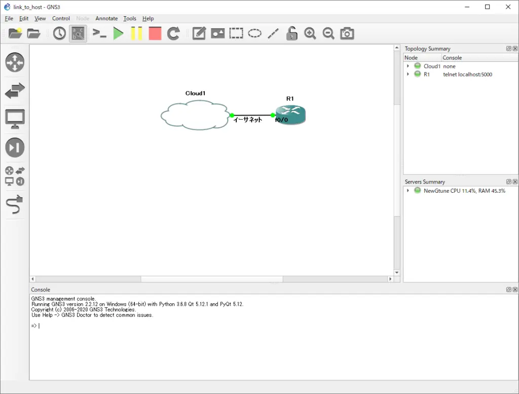
The R1 Fa0/0 is now bridged to the home network through the host.
2.DHCP Client Configuration
To enable R1 Fa0/0 to be assigned an IP address via DHCP from the BB router. enter the following command from the R1 console.
R1
interface FastEthernet0/0
 ip address dhcp
 no shutdown
sYou can use the show dhcp lease command to verify IP addresses and other information assigned by DHCP. It also registers the default route in the routing table. The next hop of the default route is the IP address of the default gateway as notified by DHCP.
R1
R1#show dhcp lease
Temp IP addr: 192.168.1.26  for peer on Interface: FastEthernet0/0
Temp  sub net mask: 255.255.255.0
   DHCP Lease server: 192.168.1.1, state: 3 Bound
   DHCP transaction id: 333
   Lease: 86400 secs,  Renewal: 43200 secs,  Rebind: 75600 secs
Temp default-gateway addr: 192.168.1.1
   Next timer fires after: 11:56:51
   Retry count: 0   Client-ID: cisco-cc01.05ac.0000-Fa0/0
   Client-ID hex dump: 636973636F2D636330312E303561632E
                       303030302D4661302F30
   Hostname: R1
R1#show ip route
Codes: C - connected, S - static, R - RIP, M - mobile, B - BGP
       D - EIGRP, EX - EIGRP external, O - OSPF, IA - OSPF inter area
       N1 - OSPF NSSA external type 1, N2 - OSPF NSSA external type 2
       E1 - OSPF external type 1, E2 - OSPF external type 2
       i - IS-IS, su - IS-IS summary, L1 - IS-IS level-1, L2 - IS-IS level-2
       ia - IS-IS inter area, * - candidate default, U - per-user static route
       o - ODR, P - periodic downloaded static route

Gateway of last resort is 192.168.1.1 to network 0.0.0.0

C    192.168.1.0/24 is directly connected, FastEthernet0/0
S*   0.0.0.0/0 [254/0] via 192.168.1.1
3.Verifying communication between R1 and the Internet
Verify the communication between R1 and the Internet: ping Google’s Public DNS server at IP address 8.8.8.8.8 and you’ll get a response, indicating that you have a connection to the Internet.
R1
R1#ping 8.8.8.8

Type escape sequence to abort.
Sending 5, 100-byte ICMP Echos to 8.8.8.8, timeout is 2 seconds:
!!!!!
Success rate is 100 percent (5/5), round-trip min/avg/max = 4/10/12 ms
How to use GNS3
- Installation of GNS3 (Windows10)
- How to Upgrade GNS3 version
- How to download IOS of the real router to PC
- Creating IOS Router Template
- Setting up the GNS3 VM server
- What to do when GNS3 VM does not turn green in Servers Summary?
- Creating an IOS router template (VM server)
- How to Use IOU(IOS on Unix) on GNS3
- How to Use CSR1000v on GNS3
- Creating GNS3 project
- Link to Host OS
- Example of linking to the host OS
- How to add a VMware virtual machine to a GNS3 topology
- VPCS Configuration and Operation
- How to Add Docker Container Linux Hosts
- How to use FRR (Free Range Routing) container on GNS3
- How to Use GNS3 Appliances
- Managing Snapshots
- Export/Import configuration
- Packet Capture
- Edit startup-config directly
- How to change the Solar-PuTTY font and background color