
Table of Contents
概要
MPLS-VPNに接続しているカスタマーに共通したサービスを提供するためのセントラルサービスVPNの設定を行います。RT(Route Target)によって、各VRFにルート情報を登録することが重要なポイントです。
ネットワーク構成
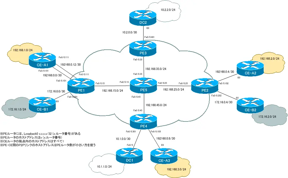
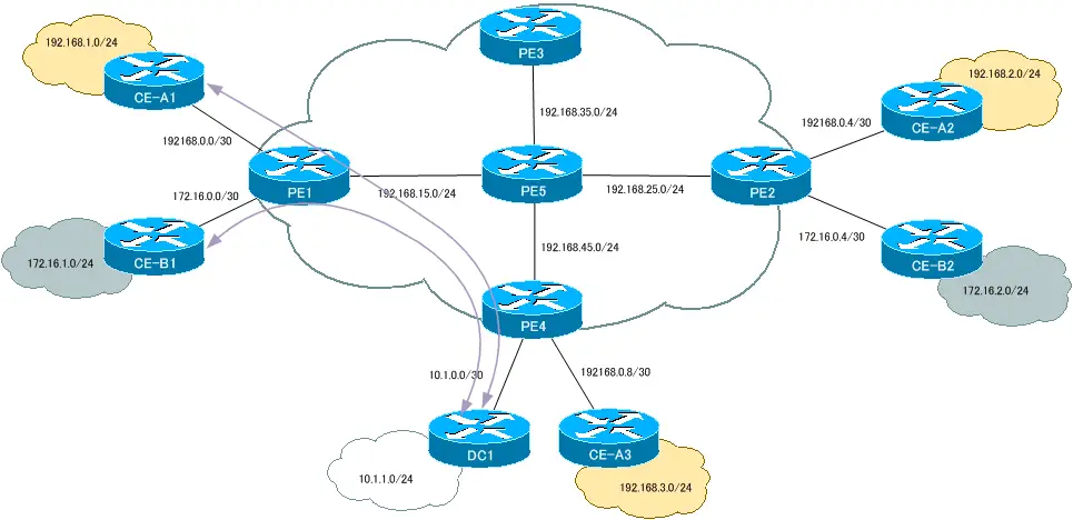
A社拠点1とB社拠点1からデータセンターDC1に通信できるようにセントラルサービスVPNを構成します。
初期設定
以下のリンクのエクストラネットのMPLS-VPNの設定が完了している状態から開始します。
DC1を接続するための設定
追加でDC1の拠点を接続するために次の設定を行います。
- PE4でDC1用のVRFを作成
- DC1用のVRFルーティングの設定
- DC1のルーティングの設定
設定するための情報は、次の表にまとめています。
| ルータ | VRF名 | RD | Import RT | Export RT | インタフェース |
| PE4 | DC1 | 300:1 | 300:1 | 300:1 | Fa0/0.301 |
| PEルータ | 拠点(VRF) | ルーティング方法 |
| PE4 | DC1(DC1) | スタティックルート |
| CEルータ | ルーティング方法 |
| DC1 | スタティックルート(デフォルトルート) |
PE4 DC1の接続
ip vrf DC1
 rd 300:1
 route-target export 300:1
 route-target import 300:1

interface FastEthernet0/0.301
 encapsulation isl 301
 ip vrf forwarding DC1
 ip address 10.1.0.1 255.255.255.252

router bgp 65000

 address-family ipv4 vrf DC1
 redistribute connected
 redistribute static

ip route vrf DC1 10.1.1.0 255.255.255.0 10.1.0.2
DC1
ip route 0.0.0.0 0.0.0.0 10.1.0.1
PE1でRTの追加設定
PE1のCustomer_A1とCustomer_B1のVRFルーティングテーブルにDC1のルート情報を登録できるように、追加のRTを設定します。
| ルータ | VRF名 | RD | Import RT | Export RT | インタフェース |
| PE1 | Customer_A1 | 100:1 | 100:1 500:500 300:1 | 100:1 500:500 300:1 | Fa0/0.101 |
| Customer_B1 | 200:1 | 200:1 500:500 300:1 | 200:1 500:500 300:1 | Fa0/0.201 |
PE1 追加のRTの設定
ip vrf Customer_A1
 route-target export 300:1
 route-target import 300:1
!
ip vrf Customer_B1
 route-target export 300:1
 route-target import 300:1
VRFルーティングテーブルの確認
PE1のCustomer_A1とCustomer_B1のVRFに追加のRTを設定することで、各VRFのルーティングテーブルは次のように変わります。
PE1 VRFルーティングテーブル
PE1#show ip route vrf Customer_A1
~省略~

Gateway of last resort is not set

     172.16.0.0/16 is variably subnetted, 2 subnets, 2 masks
B       172.16.0.0/30 is directly connected, 01:09:12, FastEthernet0/0.201
B       172.16.1.0/24 [20/0] via 172.16.0.2 (Customer_B1), 00:16:09
     10.0.0.0/8 is variably subnetted, 2 subnets, 2 masks
B       10.1.1.0/24 [200/0] via 4.4.4.4, 00:17:24
B       10.1.0.0/30 [200/0] via 4.4.4.4, 00:17:24
     192.168.0.0/30 is subnetted, 3 subnets
B       192.168.0.8 [200/0] via 4.4.4.4, 01:53:00
C       192.168.0.0 is directly connected, FastEthernet0/0.101
B       192.168.0.4 [200/0] via 2.2.2.2, 00:07:54
B    192.168.1.0/24 [20/0] via 192.168.0.2, 00:16:49
B    192.168.2.0/24 [200/0] via 2.2.2.2, 00:07:54
B    192.168.3.0/24 [200/0] via 4.4.4.4, 01:53:01
PE1#show ip route vrf Customer_B1
~省略~

Gateway of last resort is not set

     172.16.0.0/16 is variably subnetted, 4 subnets, 2 masks
B       172.16.0.4/30 [200/0] via 2.2.2.2, 00:08:01
C       172.16.0.0/30 is directly connected, FastEthernet0/0.201
B       172.16.1.0/24 [20/0] via 172.16.0.2, 00:16:29
B       172.16.2.0/24 [200/0] via 2.2.2.2, 00:08:01
     10.0.0.0/8 is variably subnetted, 2 subnets, 2 masks
B       10.1.1.0/24 [200/0] via 4.4.4.4, 00:17:17
B       10.1.0.0/30 [200/0] via 4.4.4.4, 00:17:17
     192.168.0.0/30 is subnetted, 1 subnets
B       192.168.0.0 is directly connected, 01:09:22, FastEthernet0/0.101
B    192.168.1.0/24 [20/0] via 192.168.0.2 (Customer_A1), 00:16:49
PE1のVRF「Customer_A1」のルーティングテーブルにDC1の10.1.1.0/24のルート情報が登録されています。同様にVRF「Customer_B1」のルーティングテーブルにDC1の10.1.1.0/24のルート情報が登録されています。
また、PE4のVRF DC1のルーティングテーブルは次のようになります。
PE4 VRFルーティングテーブル
PE4#show ip route vrf DC1
~省略~

Gateway of last resort is not set

     172.16.0.0/16 is variably subnetted, 2 subnets, 2 masks
B       172.16.0.0/30 [200/0] via 1.1.1.1, 00:19:26
B       172.16.1.0/24 [200/0] via 1.1.1.1, 00:18:41
     10.0.0.0/8 is variably subnetted, 2 subnets, 2 masks
S       10.1.1.0/24 [1/0] via 10.1.0.2
C       10.1.0.0/30 is directly connected, FastEthernet0/0.301
     192.168.0.0/30 is subnetted, 1 subnets
B       192.168.0.0 [200/0] via 1.1.1.1, 00:19:26
B    192.168.1.0/24 [200/0] via 1.1.1.1, 00:19:10
PE4のVRF「DC1」のルーティングテーブルには、CE-A1の192.168.1.0/24のルート情報とCE-B1の172.16.1.0/24のルート情報が登録されています。
VRFのルーティングテーブルに適切なルート情報が登録されるようになっているので、CE-A1とDC1間の通信が可能です。同様にCE-B1とDC1間の通信が可能です。

MPLS/MPLS-VPN
- MPLSラベルスイッチングの設定と確認コマンド[Cisco]
- MPLSによるラベルスイッチングの設定例 [Cisco]
- MPLSによるトランジットASの構成
- MPLS 設定ミスの切り分けと修正 Part1
- MPLS 設定ミスの切り分けと修正 Part2
- MPLS-VPNの設定例 フルメッシュ(Any-to-Any)
- MPLS-VPNの設定例 エクストラネットVPN
- MPLS-VPNの設定例 セントラルサービスVPN
- MPLS-VPNの設定例 ハブ&スポークVPN
- OSPF Sham-linkの概要
- OSPF Sham-linkの設定
- MPLS-VPN 設定ミスの切り分けと修正 Part1
- MPLS-VPN 設定ミスの切り分けと修正 Part2
- MPLS-VPN 設定ミスの切り分けと修正 Part3
- MPLS-VPN 設定ミスの切り分けと修正 Part4
- MPLS-VPN 設定ミスの切り分けと修正 Part5
- MPLS-VPN 設定ミスの切り分けと修正 Part6