目次
概要
基本的なMPLSによるラベルスイッチングの設定を行います。ルーティングテーブルをもとにMPLSラベルが割り当てられて、FIB/LFIBテーブルに基づいてパケットを転送する様子を確認します。
関連記事
ネットワーク構成
MPLSの基本的なラベルスイッチングの設定とその動作を確認します。次のネットワーク構成でMPLSによるラベルスイッチングを行います。
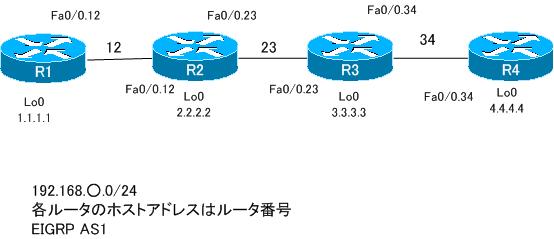
各ルータのIPアドレスの設定は次の通りです。
| ルータ | インタフェース | IPアドレス |
| R1 | Fa0/0.12 | 192.168.12.1/24 |
| Lo0 | 1.1.1.1/32 | |
| R2 | Fa0/0.12 | 192.168.12.2/24 |
| Fa0/0.23 | 192.168.23.2/24 | |
| Lo0 | 2.2.2.2/32 | |
| R3 | Fa0/0.23 | 192.168.23.3/24 |
| Fa0/0.34 | 192.168.34.3/24 | |
| Lo0 | 3.3.3.3/32 | |
| R4 | Fa0/0.34 | 192.168.34.4/24 |
| Lo0 | 4.4.4.4/32 |
また、R1~R4でルーティングプロトコルEIGRP AS1を動作させて、ルーティングができるようにしています。
設定と確認
Step1. MPLSの有効化
IPルーティングが完了している状態でMPLSによるラベルスイッチングの設定は、以下の2つを行います。
- CEFの有効化
- インタフェースでLDP or TDPの有効化
R1~R4でのMPLSによるラベルスイッチングの設定は次の通りです。
R1 MPLSの有効化
ip cef
!
interface fastethernet 0/0.12
 mpls ip
R2 MPLSの有効化
ip cef
!
interface fastethernet 0/0.12
 mpls ip
!
interface fastethernet 0/0.23
 mpls ip
R3 MPLSの有効化
ip cef
!
interface fastethernet 0/0.23
 mpls ip
!
interface fastethernet 0/0.34
 mpls ip
R4 MPLSの有効化
ip cef
!
interface fastethernet 0/0.34
 mpls ip
Step2. MPLSのインタフェース、LDPネイバーの確認
R1~R4でのMPLSの設定とLDPネイバーを確認します。show mpls interfaceによって、ラベルスイッチングが有効になっているインタフェースを確認することができます。つまり、mpls ipコマンドを入力したインタフェースがわかります。また、show mpls ldp neighborによって、LDPネイバーを確認することができます。R1のshow mpls interface、show mpls ldp neighborコマンドの例は次のようになります。
R1 show mpls interface/show mpls ldp neighbor
R1#sh mpls interfaces
Interface              IP            Tunnel   Operational
FastEthernet0/0.12     Yes (ldp)     No       Yes
R1#show mpls ldp neighbor
    Peer LDP Ident: 2.2.2.2:0; Local LDP Ident 1.1.1.1:0
        TCP connection: 2.2.2.2.43869 - 1.1.1.1.646
        State: Oper; Msgs sent/rcvd: 12/11; Downstream
        Up time: 00:01:31
        LDP discovery sources:
          FastEthernet0/0.12, Src IP addr: 192.168.12.2
        Addresses bound to peer LDP Ident:
          192.168.12.2    192.168.23.2    2.2.2.2
Step3. LIBテーブルの確認
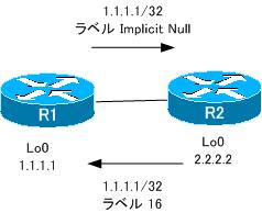
各ルータは、ルーティングテーブルのエントリごとにローカルにラベルを割り当て、LDPネイバーにアドバタイズします。ローカルに割り当てたり、LDPネイバーから受信したラベル情報はLIBテーブルに保存されます。LIBテーブルの確認には、show mpls ldp bindingsコマンドを使います。R1のLIBテーブルは次のようになります。
R1 show mpls ldp bindings
R1#show mpls ldp bindings
  tib entry: 1.1.1.1/32, rev 4
local binding:  tag: imp-null
remote binding: tsr: 2.2.2.2:0, tag: 16
  tib entry: 2.2.2.2/32, rev 6
local binding:  tag: 16
remote binding: tsr: 2.2.2.2:0, tag: imp-null
  tib entry: 3.3.3.3/32, rev 8
local binding:  tag: 17
remote binding: tsr: 2.2.2.2:0, tag: 17
  tib entry: 4.4.4.4/32, rev 10
local binding:  tag: 18
remote binding: tsr: 2.2.2.2:0, tag: 18
  tib entry: 192.168.12.0/24, rev 2
local binding:  tag: imp-null
remote binding: tsr: 2.2.2.2:0, tag: imp-null
  tib entry: 192.168.23.0/24, rev 12
local binding:  tag: 19
remote binding: tsr: 2.2.2.2:0, tag: imp-null
  tib entry: 192.168.34.0/24, rev 14
local binding:  tag: 20
remote binding: tsr: 2.2.2.2:0, tag: 19
1.1.1.1/32に対するラベルに注目してみます。このルートはR1に直接接続されているネットワークです。PHPの動作のため、直接接続されているネットワークに対してImplicit Nullのラベルを割り当てて、ネイバーに対してラベルを外すように通知しています。また、LDPネイバー2.2.2.2から1.1.1.1/32に対するラベルとして16を受信していることがわかります。
Step4. LFIBテーブルの確認
ローカルおよびリモートLSRで割り当てられたラベルを元にして、LFIBテーブルを作成します。LSRはラベル付きのパケットを受信すると、LFIBテーブルに従ってラベルの処理を行い、パケットを転送します。LFIBテーブルを確認するには、show mpls forwarding-tableコマンドを使います。R1でのLFIBテーブルは次のようになっています。
R1 LFIBテーブル show mpls forwarding-table
R1#show mpls forwarding-table
Local  Outgoing    Prefix            Bytes tag  Outgoing   Next Hop
tag    tag or VC   or Tunnel Id      switched   interface
16     Pop tag     2.2.2.2/32        0          Fa0/0.12   192.168.12.2
17     17          3.3.3.3/32        0          Fa0/0.12   192.168.12.2
18     18          4.4.4.4/32        0          Fa0/0.12   192.168.12.2
19     Pop tag     192.168.23.0/24   0          Fa0/0.12   192.168.12.2
20     19          192.168.34.0/24   0          Fa0/0.12   192.168.12.2
Step5. FIBテーブルの確認
CEFによるパケットスイッチングでは、FIBテーブルを参照してIPパケットを転送します。MPLSが有効になっている場合、FIBテーブルにラベル情報も含まれるようになります。FIBテーブルを確認するには、show ip cefコマンドを使います。なお、FIBテーブルに含まれるラベル情報を参照するには、show ip cef detailコマンドを使います。たとえば、R1ではFIBテーブルは次のようになります。
R1 show ip cef
R1#show ip cef
Prefix              Next Hop             Interface
0.0.0.0/32          receive
1.1.1.1/32          receive
2.2.2.2/32          192.168.12.2         FastEthernet0/0.12
3.3.3.3/32          192.168.12.2         FastEthernet0/0.12
4.4.4.4/32          192.168.12.2         FastEthernet0/0.12
192.168.12.0/24     attached             FastEthernet0/0.12
192.168.12.0/32     receive
192.168.12.1/32     receive
192.168.12.2/32     192.168.12.2         FastEthernet0/0.12
192.168.12.255/32   receive
192.168.23.0/24     192.168.12.2         FastEthernet0/0.12
192.168.34.0/24     192.168.12.2         FastEthernet0/0.12
224.0.0.0/4         drop
224.0.0.0/24        receive
255.255.255.255/32  receive
R1#show ip cef detail
IP CEF with switching (Table Version 12), flags=0x0
  12 routes, 0 reresolve, 0 unresolved (0 old, 0 new), peak 0
  15 leaves, 23 nodes, 25720 bytes, 15 inserts, 0 invalidations
  0 load sharing elements, 0 bytes, 0 references
  universal per-destination load sharing algorithm, id BCB9E1FF
  2(0) CEF resets, 0 revisions of existing leaves
  Resolution Timer: Exponential (currently 1s, peak 1s)
  0 in-place/0 aborted modifications
  refcounts:  810 leaf, 813 node

Adjacency Table has 2 adjacencies
0.0.0.0/32, version 0, receive
1.1.1.1/32, version 4, connected, receive
  tag information set
    local tag: implicit-null
2.2.2.2/32, version 6, cached adjacency 192.168.12.2
0 packets, 0 bytes
  tag information set
    local tag: 16
  via 192.168.12.2, FastEthernet0/0.12, 0 dependencies
    next hop 192.168.12.2, FastEthernet0/0.12
    valid cached adjacency
    tag rewrite with Fa0/0.12, 192.168.12.2, tags imposed: {}
3.3.3.3/32, version 7, cached adjacency 192.168.12.2
0 packets, 0 bytes
  tag information set
    local tag: 17
    fast tag rewrite with Fa0/0.12, 192.168.12.2, tags imposed: {17}
  via 192.168.12.2, FastEthernet0/0.12, 0 dependencies
    next hop 192.168.12.2, FastEthernet0/0.12
    valid cached adjacency
    tag rewrite with Fa0/0.12, 192.168.12.2, tags imposed: {17}
4.4.4.4/32, version 8, cached adjacency 192.168.12.2
0 packets, 0 bytes
  tag information set
    local tag: 18
    fast tag rewrite with Fa0/0.12, 192.168.12.2, tags imposed: {18}
  via 192.168.12.2, FastEthernet0/0.12, 0 dependencies
    next hop 192.168.12.2, FastEthernet0/0.12
    valid cached adjacency
    tag rewrite with Fa0/0.12, 192.168.12.2, tags imposed: {18}
~省略~
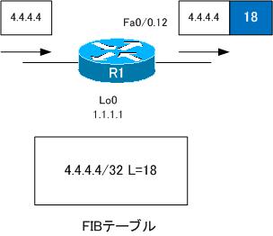
show ip cef detailの4.4.4.4/32の情報について注目すると、ローカルタグとLDPネイバーであるR2から受信したラベル情報が含まれていることがわかります。R1は、4.4.4.4あてのIPパケットを受信すると、この情報に基づいてラベル18を付加してFa0/0.12から出力します。
Step6. R1から4.4.4.4/32までのLSPの確認
MPLSによってR1からR4の間でラベルスイッチによるパケット転送が可能です。どのようにIPパケットにラベルが付加されて転送されていくかという
LSP(Label Switched Path)を確認してみましょう。R1からR4の4.4.4.4へIPパケットが転送されていく経路をみることにします。
R1はMPLSネットワークとIPネットワークの境界にあたるエッジLSRです。そのため、R1にはラベルがついていない通常のIPパケットが届くはずです。通常のIPパケットを転送するには、FIBテーブルを参照します。R1で4.4.4.4/32に対するFIBテーブルのエントリは次のようになっています。
R1 4.4.4.4/32に対するFIBテーブルエントリ
R1#show ip cef 4.4.4.4
4.4.4.4/32, version 8, cached adjacency 192.168.12.2
0 packets, 0 bytes
  tag information set
    local tag: 18
    fast tag rewrite with Fa0/0.12, 192.168.12.2, tags imposed: {18}
  via 192.168.12.2, FastEthernet0/0.12, 0 dependencies
    next hop 192.168.12.2, FastEthernet0/0.12
    valid cached adjacency
    tag rewrite with Fa0/0.12, 192.168.12.2, tags imposed: {18}
Step5でも確認しましたが、R1は4.4.4.4あてのIPパケットにラベル18を付加して、Fa0/0.12から出力することがわかります。
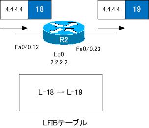
ラベルが付加されたパケットはR2に届きます。R2ではLFIBテーブルによってラベル付きパケットを転送することになります。R2のLFIBテーブルは次の通りです。
R2 LFIBテーブル
R2#show mpls forwarding-table
Local  Outgoing    Prefix            Bytes tag  Outgoing   Next Hop
tag    tag or VC   or Tunnel Id      switched   interface
16     Pop tag     1.1.1.1/32        0          Fa0/0.12   192.168.12.1
17     Pop tag     3.3.3.3/32        0          Fa0/0.23   192.168.23.3
18     19          4.4.4.4/32        0          Fa0/0.23   192.168.23.3
19     Pop tag     192.168.34.0/24   0          Fa0/0.23   192.168.23.3
R2のLFIBテーブルから、ラベル18が付加されているパケットはラベル19に書き換えてFa0/0.23から出力することがわかります。
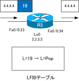
R2でラベル19に書き換えられたパケットはR3に届きます。R3ではLFIBテーブルによってそのパケットを転送します。R3のLFIBテーブルは次の通りです。
R3 LFIBテーブル
R3#show mpls forwarding-table
Local  Outgoing    Prefix            Bytes tag  Outgoing   Next Hop
tag    tag or VC   or Tunnel Id      switched   interface
16     Pop tag     192.168.12.0/24   0          Fa0/0.23   192.168.23.2
17     16          1.1.1.1/32        0          Fa0/0.23   192.168.23.2
18     Pop tag     2.2.2.2/32        0          Fa0/0.23   192.168.23.2
19     Pop tag     4.4.4.4/32        0          Fa0/0.34   192.168.34.4
R3ではラベル19が付加されているパケットは、ラベルを取り除いて(Popして)Fa0/0.34に転送することがわかります。ラベルを取り除くのは、PHP(Penultimate Hop Popping)のためです。4.4.4.4へのLSPの最後から2番目のルータでR3がラベルを取り除くことで、LSPの最後のルータであるR4での余分なテーブルの検索を防ぎます。
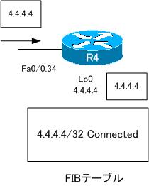
R4には通常のIPパケットが届きます。そのため、R4はFIBテーブルを参照して自身のLoopback0のインタフェースへパケットをルーティングします。
R4 FIBテーブル
R4#show ip cef 4.4.4.4
4.4.4.4/32, version 4, connected, receive
  tag information set
    local tag: implicit-null

MPLS/MPLS-VPN
- MPLSラベルスイッチングの設定と確認コマンド[Cisco]
- MPLSによるラベルスイッチングの設定例 [Cisco]
- MPLSによるトランジットASの構成
- MPLS 設定ミスの切り分けと修正 Part1
- MPLS 設定ミスの切り分けと修正 Part2
- MPLS-VPNの設定例 フルメッシュ(Any-to-Any)
- MPLS-VPNの設定例 エクストラネットVPN
- MPLS-VPNの設定例 セントラルサービスVPN
- MPLS-VPNの設定例 ハブ&スポークVPN
- OSPF Sham-linkの概要
- OSPF Sham-linkの設定
- MPLS-VPN 設定ミスの切り分けと修正 Part1
- MPLS-VPN 設定ミスの切り分けと修正 Part2
- MPLS-VPN 設定ミスの切り分けと修正 Part3
- MPLS-VPN 設定ミスの切り分けと修正 Part4
- MPLS-VPN 設定ミスの切り分けと修正 Part5
- MPLS-VPN 設定ミスの切り分けと修正 Part6