目次
概要
MPLS-VPNのPEルータで、VRFのルーティング設定を正しく行う必要があります。VRFのルーティングの設定ミスについて、切り分けと修正を行います。
ネットワーク構成
下記のネットワーク構成で、MPLS-VPNを通じてR4とR5間の通信ができるようにしたいと考えています。
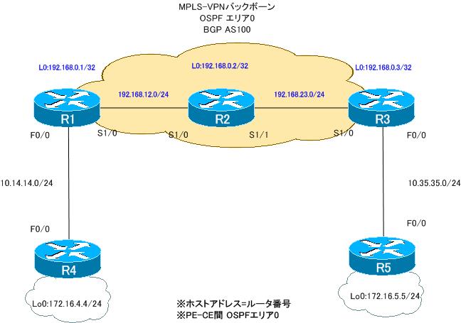
ルータの役割は、次の通りです。
PEルータ:R1、R3
Pルータ :R2
CEルータ:R4、R5
PEルータであるR1、R3ではともにVRFとして次のように定義します。
VRF名:VPN
RD:100:100
Import RT:100:100
Export RT:100:100
設定概要
各ルータで行われているMPLS-VPNでの通信に関連する設定は次の通りです。
R1
ip vrf VPN
 rd 100:100
 route-target export 100:100
 route-target import 100:101
!
interface Loopback0
 ip address 192.168.0.1 255.255.255.255
!
interface FastEthernet0/0
 ip vrf forwarding VPN
 ip address 10.14.14.1 255.255.255.0
!
interface Serial1/0
 ip address 192.168.12.1 255.255.255.0
 encapsulation ppp
 mpls ip
 no peer neighbor-route
!
router ospf 14 vrf VPN
 log-adjacency-changes
 redistribute bgp 100 subnets
 network 10.14.14.1 0.0.0.0 area 0
!
router ospf 1
 log-adjacency-changes
 network 192.168.0.0 0.0.255.255 area 0
!
router bgp 100
 no synchronization
 bgp log-neighbor-changes
 neighbor 192.168.0.3 remote-as 100
 neighbor 192.168.0.3 update-source Loopback0
 no auto-summary
 !
 address-family vpnv4
  neighbor 192.168.0.3 activate
  neighbor 192.168.0.3 send-community extended
 exit-address-family
 !
 address-family ipv4 vrf VPN
  no synchronization
 exit-address-family
R2
interface Loopback0
 ip address 192.168.0.2 255.255.255.255
!
interface Serial1/0
 ip address 192.168.12.2 255.255.255.0
 encapsulation ppp
 mpls ip
 no peer neighbor-route
!
interface Serial1/1
 ip address 192.168.23.2 255.255.255.0
 encapsulation ppp
 mpls ip
 no peer neighbor-route
!
router ospf 1
 log-adjacency-changes
 network 192.168.0.0 0.0.255.255 area 0
R3
ip vrf VPN
 rd 100:100
 route-target export 100:100
 route-target import 100:100
!
interface Loopback0
 ip address 192.168.0.3 255.255.255.255
!
interface FastEthernet0/0
 ip vrf forwarding VPN
 ip address 10.35.35.3 255.255.255.0
 duplex auto
 speed auto
!
interface Serial1/0
 ip address 192.168.23.3 255.255.255.0
 encapsulation ppp
 mpls ip
 no peer neighbor-route
!
router ospf 35 vrf VPN
 log-adjacency-changes
 redistribute bgp 100 subnets
 network 10.35.35.3 0.0.0.0 area 0
!
router ospf 1
 log-adjacency-changes
 network 192.168.0.0 0.0.255.255 area 0
!
router bgp 100
 no synchronization
 bgp log-neighbor-changes
 neighbor 192.168.0.1 remote-as 100
 neighbor 192.168.0.1 update-source Loopback0
 no auto-summary
 !
 address-family vpnv4
  neighbor 192.168.0.1 activate
  neighbor 192.168.0.1 send-community extended
 exit-address-family
 !
 address-family ipv4 vrf VPN
  redistribute ospf 35 vrf VPN
  no synchronization
 exit-address-family
R4
interface Loopback0
 ip address 172.16.4.4 255.255.255.0
 ip ospf network point-to-point
!
interface FastEthernet0/0
 ip address 10.14.14.4 255.255.255.0
!
router ospf 1
 log-adjacency-changes
 network 10.14.14.4 0.0.0.0 area 0
 network 172.16.4.4 0.0.0.0 area 0
R5
interface Loopback0
 ip address 172.16.5.5 255.255.255.0
 ip ospf network point-to-point
!
interface FastEthernet0/0
 ip address 10.35.35.5 255.255.255.0
!
router ospf 1
 log-adjacency-changes
 network 10.35.35.5 0.0.0.0 area 0
 network 172.16.5.5 0.0.0.0 area 0
トラブルの症状
R4、R5でルーティングテーブルを見るとお互いのルートを確認できません。そのため、当然、通信が不可能な状態になってしまっています。R4のルーティングテーブルと、R5への通信の結果は次のようになっています。
R4 show ip route/ping 172.16.5.5
R4#sh ip route
~省略~
Gateway of last resort is not set

     172.16.0.0/24 is subnetted, 1 subnets
C       172.16.4.0 is directly connected, Loopback0
     10.0.0.0/24 is subnetted, 1 subnets
C       10.14.14.0 is directly connected, FastEthernet0/0
R4#ping 172.16.5.5 source 172.16.4.4

Type escape sequence to abort.
Sending 5, 100-byte ICMP Echos to 172.16.5.5, timeout is 2 seconds:
Packet sent with a source address of 172.16.4.4
.....
Success rate is 0 percent (0/5)
PEルータであるR1、R3とCEルータであるR4、R5はOSPFでルーティングを行っています。ネイバーを確認すると、次のように正常にOSPFネイバーを確認できています。
R4 show ip ospf neighbor
R4#sh ip ospf neighbor

Neighbor ID     Pri   State           Dead Time   Address         Interface
10.14.14.1        1   FULL/BDR        00:00:34    10.14.14.1      FastEthernet0/0
R5 show ip ospf neighbor
R5#show ip ospf neighbor

Neighbor ID     Pri   State           Dead Time   Address         Interface
10.35.35.3        1   FULL/BDR        00:00:38    10.35.35.3      FastEthernet0/0
そのため、PE-CE間のルーティングには特に問題がないと考えられます。問題はMPLSバックボーンにある可能性が高いです。そこでMPLSバックボーンを構成するR1、R2、R3で次のshowコマンドで原因の切り分けを行いました。
R1
show mpls interface
show mpls ldp neighbor
show ip vrf detail
show ip bgp vpnv4 all
show ip route vrf VPN
R2
show mpls interface
show mpls ldp neighbor
R3
show mpls interface
show mpls ldp neighbor
show ip vrf detail
show ip bgp vpnv4 all
show ip route vrf VPN
R1 showコマンドの結果
R1#show mpls interface
Interface              IP            Tunnel   Operational
Serial1/0              Yes (ldp)     No       Yes
R1#show mpls ldp neighbor
    Peer LDP Ident: 192.168.0.2:0; Local LDP Ident 192.168.0.1:0
        TCP connection: 192.168.0.2.18981 - 192.168.0.1.646
        State: Oper; Msgs sent/rcvd: 27/27; Downstream
        Up time: 00:17:08
        LDP discovery sources:
          Serial1/0, Src IP addr: 192.168.12.2
        Addresses bound to peer LDP Ident:
          192.168.12.2    192.168.0.2     192.168.23.2
R1#show ip vrf detail
VRF VPN; default RD 100:100; default VPNID
  Interfaces:
    Fa0/0
  Connected addresses are not in global routing table
  Export VPN route-target communities
    RT:100:100
  Import VPN route-target communities
    RT:100:101
  No import route-map
  No export route-map
  VRF label distribution protocol: not configured
R1#show ip bgp vpnv4 all

R1#show ip route vrf VPN

Routing Table: VPN
Codes: C - connected, S - static, R - RIP, M - mobile, B - BGP
       D - EIGRP, EX - EIGRP external, O - OSPF, IA - OSPF inter area
       N1 - OSPF NSSA external type 1, N2 - OSPF NSSA external type 2
       E1 - OSPF external type 1, E2 - OSPF external type 2
       i - IS-IS, su - IS-IS summary, L1 - IS-IS level-1, L2 - IS-IS level-2
       ia - IS-IS inter area, * - candidate default, U - per-user static route
       o - ODR, P - periodic downloaded static route

Gateway of last resort is not set

     172.16.0.0/24 is subnetted, 1 subnets
O       172.16.4.0 [110/2] via 10.14.14.4, 00:16:35, FastEthernet0/0
     10.0.0.0/24 is subnetted, 1 subnets
C       10.14.14.0 is directly connected, FastEthernet0/0
R2 showコマンドの結果
R2#show mpls interface
Interface              IP            Tunnel   Operational
Serial1/0              Yes (ldp)     No       Yes
Serial1/1              Yes (ldp)     No       Yes
R2#show mpls ldp neighbor
    Peer LDP Ident: 192.168.0.1:0; Local LDP Ident 192.168.0.2:0
        TCP connection: 192.168.0.1.646 - 192.168.0.2.18981
        State: Oper; Msgs sent/rcvd: 28/29; Downstream
        Up time: 00:18:12
        LDP discovery sources:
          Serial1/0, Src IP addr: 192.168.12.1
        Addresses bound to peer LDP Ident:
          192.168.0.1     192.168.12.1
    Peer LDP Ident: 192.168.0.3:0; Local LDP Ident 192.168.0.2:0
        TCP connection: 192.168.0.3.20001 - 192.168.0.2.646
        State: Oper; Msgs sent/rcvd: 29/28; Downstream
        Up time: 00:18:10
        LDP discovery sources:
          Serial1/1, Src IP addr: 192.168.23.3
        Addresses bound to peer LDP Ident:
          192.168.0.3     192.168.23.3
R3 showコマンドの結果
R3#show mpls interface
Interface              IP            Tunnel   Operational
Serial1/0              Yes (ldp)     No       Yes
R3#show mpls ldp neighbor
    Peer LDP Ident: 192.168.0.2:0; Local LDP Ident 192.168.0.3:0
        TCP connection: 192.168.0.2.646 - 192.168.0.3.20001
        State: Oper; Msgs sent/rcvd: 29/30; Downstream
        Up time: 00:18:49
        LDP discovery sources:
          Serial1/0, Src IP addr: 192.168.23.2
        Addresses bound to peer LDP Ident:
          192.168.12.2    192.168.0.2     192.168.23.2
R3#show ip vrf detail
VRF VPN; default RD 100:100; default VPNID
  Interfaces:
    Fa0/0
  Connected addresses are not in global routing table
  Export VPN route-target communities
    RT:100:100
  Import VPN route-target communities
    RT:100:100
  No import route-map
  No export route-map
  VRF label distribution protocol: not configured
R3#show ip bgp vpnv4 all
BGP table version is 11, local router ID is 192.168.0.3
Status codes: s suppressed, d damped, h history, * valid, > best, i - internal,
              r RIB-failure, S Stale
Origin codes: i - IGP, e - EGP, ? - incomplete

   Network          Next Hop            Metric LocPrf Weight Path
Route Distinguisher: 100:100 (default for vrf VPN)
*> 10.35.35.0/24    0.0.0.0                  0         32768 ?
*> 172.16.5.0/24    10.35.35.5               2         32768 ?
R3#show ip route vrf VPN

Routing Table: VPN
Codes: C - connected, S - static, R - RIP, M - mobile, B - BGP
       D - EIGRP, EX - EIGRP external, O - OSPF, IA - OSPF inter area
       N1 - OSPF NSSA external type 1, N2 - OSPF NSSA external type 2
       E1 - OSPF external type 1, E2 - OSPF external type 2
       i - IS-IS, su - IS-IS summary, L1 - IS-IS level-1, L2 - IS-IS level-2
       ia - IS-IS inter area, * - candidate default, U - per-user static route
       o - ODR, P - periodic downloaded static route

Gateway of last resort is not set

     172.16.0.0/24 is subnetted, 1 subnets
O       172.16.5.0 [110/2] via 10.35.35.5, 00:18:18, FastEthernet0/0
     10.0.0.0/24 is subnetted, 1 subnets
C       10.35.35.0 is directly connected, FastEthernet0/0
R1~R3のshowコマンドによって設定ミスがわかったので修正すると、正常にMPLS-VPNを通じてR4-R5間の通信ができるようになりました。
問題
- PE-CE間のルーティングには問題がないのに、R4-R5間で通信できない理由はなんですか?
- MPLS-VPN経由でR4-R5間の通信ができるようにするためには、どのように設定を修正すればよいですか?
解答
PE-CE間のルーティングには問題がないのに、R4-R5間で通信できない理由はなんですか?
R1でVRF「VPN」のImport RTの設定が間違っているため、R2からのMP-BGPのルートを正しく受信できていない。
また、R1でVRF「VPN」のOSPFルートをMP-BGPへ再配送する設定が抜けている。そのため、R1からR3へMP-BGPルートが送信されない。上記の2点の設定ミスのため、R4、R5に必要なルートが伝わらず、通信できない
MPLS-VPN経由でR4-R5間の通信ができるようにするためには、どのように設定を修正すればよいですか?
R1
ip vrf VPN
 no route-target import
 route-target import 100:100
!
router bgp 100
 address-family ipv4 vrf VPN
  redistribute ospf 14
解説
今回の設定ミスは、次の2点です。
- RTのミス
- 再配送の設定漏れ
【RTのミス】
まず、RTの仕組みを簡単に解説し、RTのミスについて考えます。MPLS-VPNバックボーンのPEルータ間で、MP-BGPによって接続しているサイトのVPNルートを交換します。MP-BGPのそれぞれのルートには、VRFを識別するためにRoute Target(RT)が付加されています。RTはとても重要です。MP-BGPのルートのRTを見て、そのルートをどのVRFで扱うべきかを決めています。次の図は、RTによってMP-BGPルートを扱うVRFを決めている様子を簡単に表しています。
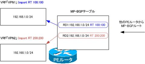
PEルータのMP-BGPテーブルには、次の2つのMP-BGPルートがあります。
- RD1:192.168.1.0/24 RT100:100
- RD2:192.168.1.0/24 RT200:200
そして、PEルータには「VPN1」と「VPN2」のVRFがあります。VPN1のVRFはImport RTとして100:100が決められています。そのため、VPN1のVRFで扱うMP-BGPルートはRT 100:100が付加されている1.のルートです。同様に考えてVPN2のVRFで扱うルートはRT 200:200が付加されている2.のルートになります。このようにRTによって、どのVRFでMP-BGPルートを扱うかを決定しているので、RTが正しくなければルートがうまく伝わりません。
ここで問題の構成のPEルータであるR1とR3でのRTについて確認します。VRFのRTはshow ip vrf detailでわかります。
R1 show ip vrf detail
R1#show ip vrf detail VRF VPN; default RD 100:100; default VPNIDInterfaces: Fa0/0 Connected addresses are not in global routing table Export VPN route-target communities RT:100:100 Import VPN route-target communities RT:100:101 No import route-map No export route-map VRF label distribution protocol: not configured
R3 show ip vrf detail
R3#show ip vrf detail VRF VPN; default RD 100:100; default VPNIDInterfaces: Fa0/0 Connected addresses are not in global routing table Export VPN route-target communities RT:100:100 Import VPN route-target communities RT:100:100 No import route-map No export route-map VRF label distribution protocol: not configured
R1はVRF「VPN」について、
Import RT 100:101
Export RT 100:100
が設定されていることがわかります。そして、R3ではVRF「VPN」について
Import RT 100:100
Export RT 100:100
が設定されています。
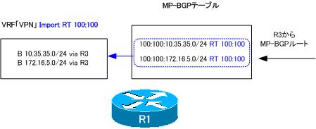
R3からは、RT 100:100が付加されるのですが、それを扱うべきR1のVRF「VPN」のImport RTの設定が間違っています。R1のVRF「VPN」のImport RTを100:100にしなければいけません。次の設定は、R1のVRF「VPN」のImport RTを100:100にするためのものです。
R1 Import RTの修正
ip vrf VPN
 no route-target import
 route-target import 100:100
R1でImport RTを修正すると、MP-BGPテーブルは次のようにR3から受信したルートを確認できるようになります。また、VRF「VPN」のルーティングテーブルにR3から受信したルートがBGPルートとして登録されます。
R1 show ip bgp vpnv4 all/show ip route vrf VPN
R1#show ip bgp vpnv4 all
BGP table version is 3, local router ID is 192.168.0.1
Status codes: s suppressed, d damped, h history, * valid, > best, i - internal,
              r RIB-failure, S Stale
Origin codes: i - IGP, e - EGP, ? - incomplete

   Network          Next Hop            Metric LocPrf Weight Path
Route Distinguisher: 100:100 (default for vrf VPN)
*>i10.35.35.0/24    192.168.0.3              0    100      0 ?
*>i172.16.5.0/24    192.168.0.3              2    100      0 ?
R1#show ip route vrf VPN

Routing Table: VPN
~省略~
Gateway of last resort is not set

     172.16.0.0/24 is subnetted, 2 subnets
O       172.16.4.0 [110/2] via 10.14.14.4, 00:04:57, FastEthernet0/0
B       172.16.5.0 [200/2] via 192.168.0.3, 00:04:31
     10.0.0.0/24 is subnetted, 2 subnets
B       10.35.35.0 [200/0] via 192.168.0.3, 00:04:31
C       10.14.14.0 is directly connected, FastEthernet0/0
そして、R3から受信したMP-BGPルートはVRF「VPN」のOSPFへ再配送されて、R4へアドバタイズされます。R4のルーティングテーブルを見ると、R5のネットワークのルートが登録されます。
R4 show ip route
R4#show ip route
~省略~
Gateway of last resort is not set

     172.16.0.0/24 is subnetted, 2 subnets
C       172.16.4.0 is directly connected, Loopback0
O E2    172.16.5.0 [110/2] via 10.14.14.1, 00:06:49, FastEthernet0/0
     10.0.0.0/24 is subnetted, 2 subnets
O E2    10.35.35.0 [110/1] via 10.14.14.1, 00:06:49, FastEthernet0/0
C       10.14.14.0 is directly connected, FastEthernet0/0
【再配送の設定漏れ】
R1はR4から受信したOSPFルートをMP-BGPルートとしてR3へアドバタイズしなければいけません。ですが、再配送の設定漏れのためにそれができていません。CEルータから受信したルートをMP-BGPルートとして他のPEルータへアドバタイズするためには、再配送が必要です。R1でVRF「VPN」のOSPFからMP-BGPへの再配送の設定が抜けています。R1でのVRF「VPN」のOSPFからMP-BGPの再配送に関する設定は次の通りです。
R1 VRF「VPN」のOSPFからMP-BGPへの再配送
router bgp 100
 address-family ipv4 vrf VPN
  redistribute ospf 14
再配送の設定をすることで、R1はVRF「VPN」のOSPFルート 10.14.14.0/24と172.16.4.0/24 をMP-BGPルートとして生成します。R1のMP-BGPテーブルを確認すると、次のようになります。
R1 show ip bgp vpnv4 all
R1#sh ip bgp vpnv4 all
BGP table version is 9, local router ID is 192.168.0.1
Status codes: s suppressed, d damped, h history, * valid, > best, i - internal,
              r RIB-failure, S Stale
Origin codes: i - IGP, e - EGP, ? - incomplete

   Network          Next Hop            Metric LocPrf Weight Path
Route Distinguisher: 100:100 (default for vrf VPN)
*> 10.14.14.0/24    0.0.0.0                  0         32768 ?
*>i10.35.35.0/24    192.168.0.3              0    100      0 ?
*> 172.16.4.0/24    10.14.14.4               2         32768 ?
*>i172.16.5.0/24    192.168.0.3              2    100      0 ?
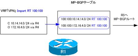
R1からR3へ10.14.14.0/24と172.16.4.0/24がアドバタイズされ、最終的にR5まで伝わります。R5のルーティングテーブルは次のようになっています。
R5 show ip route
R5#show ip route
~省略~

Gateway of last resort is not set

     172.16.0.0/24 is subnetted, 2 subnets
O E2    172.16.4.0 [110/2] via 10.35.35.3, 00:04:09, FastEthernet0/0
C       172.16.5.0 is directly connected, Loopback0
     10.0.0.0/24 is subnetted, 2 subnets
C       10.35.35.0 is directly connected, FastEthernet0/0
O E2    10.14.14.0 [110/1] via 10.35.35.3, 00:04:09, FastEthernet0/0
以上のように、
- R1でのImport RTの修正
- R1でのVRFのOSPFMP-BGPへの再配送の追加
を行うことで、R4、R5で正しくルートを学習できるようになりました。その結果、通信も可能になります。
R4、R5間の通信確認
R4#ping 172.16.5.5 source 172.16.4.4

Type escape sequence to abort.
Sending 5, 100-byte ICMP Echos to 172.16.5.5, timeout is 2 seconds:
Packet sent with a source address of 172.16.4.4
!!!!!
Success rate is 100 percent (5/5), round-trip min/avg/max = 20/39/76 ms
R5#ping 172.16.4.4 source 172.16.5.5

Type escape sequence to abort.
Sending 5, 100-byte ICMP Echos to 172.16.4.4, timeout is 2 seconds:
Packet sent with a source address of 172.16.5.5
!!!!!
Success rate is 100 percent (5/5), round-trip min/avg/max = 20/31/64 ms

MPLS/MPLS-VPN
- MPLSラベルスイッチングの設定と確認コマンド[Cisco]
- MPLSによるラベルスイッチングの設定例 [Cisco]
- MPLSによるトランジットASの構成
- MPLS 設定ミスの切り分けと修正 Part1
- MPLS 設定ミスの切り分けと修正 Part2
- MPLS-VPNの設定例 フルメッシュ(Any-to-Any)
- MPLS-VPNの設定例 エクストラネットVPN
- MPLS-VPNの設定例 セントラルサービスVPN
- MPLS-VPNの設定例 ハブ&スポークVPN
- OSPF Sham-linkの概要
- OSPF Sham-linkの設定
- MPLS-VPN 設定ミスの切り分けと修正 Part1
- MPLS-VPN 設定ミスの切り分けと修正 Part2
- MPLS-VPN 設定ミスの切り分けと修正 Part3
- MPLS-VPN 設定ミスの切り分けと修正 Part4
- MPLS-VPN 設定ミスの切り分けと修正 Part5
- MPLS-VPN 設定ミスの切り分けと修正 Part6
