Table of Contents
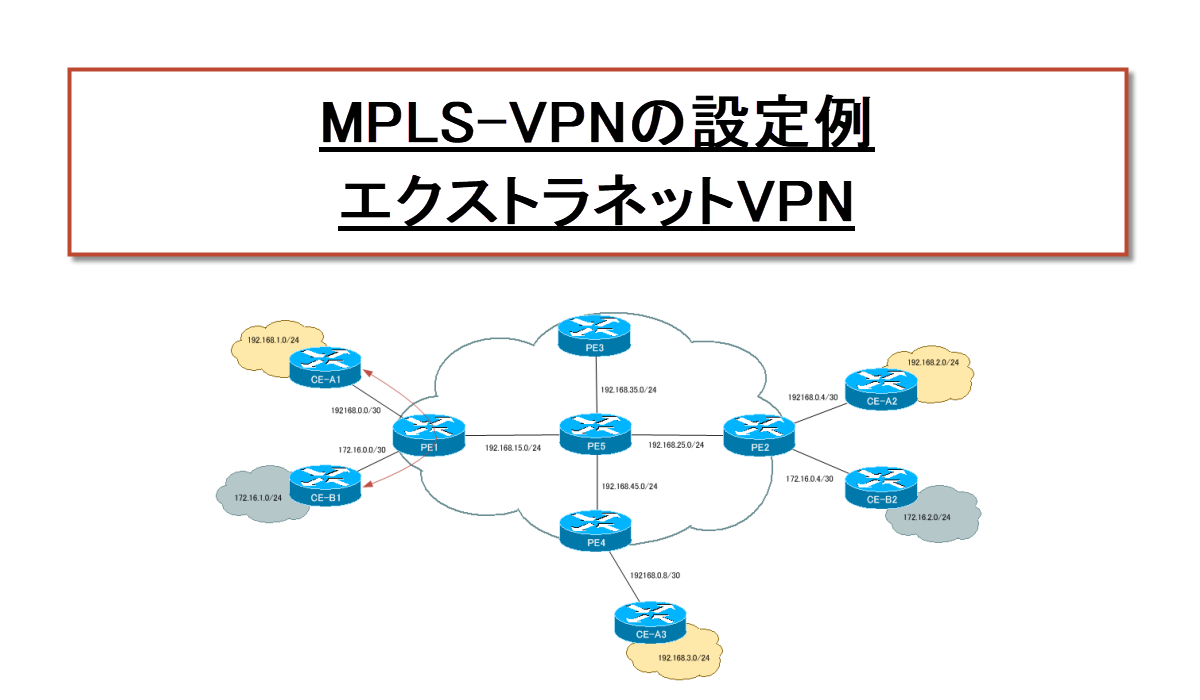
概要
MPLS-VPN経由で他社の特定のネットワークとの通信を可能にするエクストラネットVPNの設定を行います。PEルータでRT(Route Target)を追加するだけで、簡単にエクストラネットVPNを実現できます。
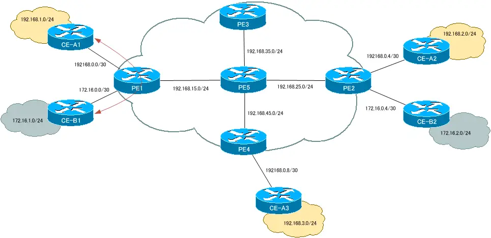
ネットワーク構成
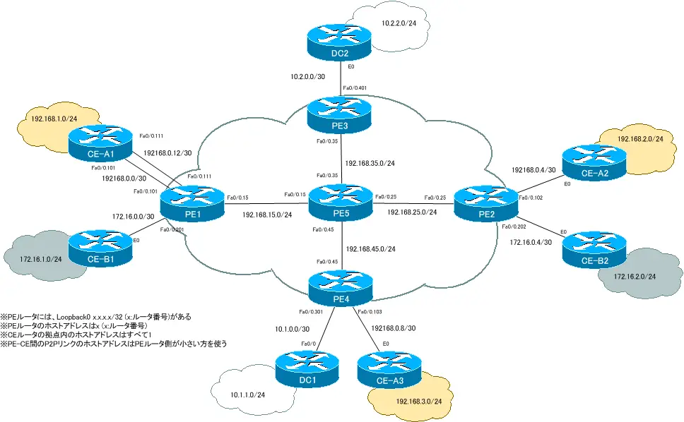
A社拠点1とB社拠点1間で通信ができるようにエクストラネットVPNを構成します。
初期設定
以下のリンクのフルメッシュのMPLS-VPNの設定が完了している状態から開始します。
RTの追加設定
A社拠点1とB社拠点1との間でエクストラネットを構成するためには、各拠点に対応するVRFルーティングテーブルに接続性を確保したいルートを登録します。そのために、追加でRTを設定します。
| ルータ | VRF名 | RD | Import RT | Export RT | インタフェース |
| PE1 | Customer_A1 | 100:1 | 100:1 500:500 | 100:1 500:500 | Fa0/0.101 |
| Customer_B1 | 200:1 | 200:1 500:500 | 200:1 500:500 | Fa0/0.201 |
PE1 追加のRTの設定
ip vrf Customer_A1
 route-target export 500:500
 route-target import 500:500
!
ip vrf Customer_B1
 route-target export 500:500
 route-target import 500:500
VRFルーティングテーブルの確認
PE1のCustomer_A1とCustomer_B1のVRFに追加のRTを設定することで、各VRFのルーティングテーブルは次のように変わります。
PE1 VRFルーティングテーブル
PE1#show ip route vrf Customer_A1
~省略~

Gateway of last resort is not set

     172.16.0.0/16 is variably subnetted, 2 subnets, 2 masks
B       172.16.0.0/30 is directly connected, 00:03:40, FastEthernet0/0.201
B       172.16.1.0/24 [20/0] via 172.16.0.2 (Customer_B1), 00:02:56
     192.168.0.0/30 is subnetted, 3 subnets
B       192.168.0.8 [200/0] via 4.4.4.4, 00:47:29
C       192.168.0.0 is directly connected, FastEthernet0/0.101
B       192.168.0.4 [200/0] via 2.2.2.2, 00:52:29
B    192.168.1.0/24 [20/0] via 192.168.0.2, 00:03:58
B    192.168.2.0/24 [200/0] via 2.2.2.2, 00:52:31
B    192.168.3.0/24 [200/0] via 4.4.4.4, 00:47:30
PE1#show ip route vrf Customer_B1
~省略~

Gateway of last resort is not set

     172.16.0.0/16 is variably subnetted, 4 subnets, 2 masks
B       172.16.0.4/30 [200/0] via 2.2.2.2, 00:52:40
C       172.16.0.0/30 is directly connected, FastEthernet0/0.201
B       172.16.1.0/24 [20/0] via 172.16.0.2, 00:03:17
B       172.16.2.0/24 [200/0] via 2.2.2.2, 00:52:40
     192.168.0.0/30 is subnetted, 1 subnets
B       192.168.0.0 is directly connected, 00:03:51, FastEthernet0/0.101
B    192.168.1.0/24 [20/0] via 192.168.0.2 (Customer_A1), 00:04:06
A社の拠点1に対応するVRF Customer_A1のルーティングテーブルにB社拠点1のルート情報が登録されています。同様にB社の拠点1に対するVRF Customer_B1のルーティングテーブルにA社拠点1のルート情報が登録されています。これにより、A社拠点1とB社拠点1間で通信が可能になります。

MPLS/MPLS-VPN
- MPLSラベルスイッチングの設定と確認コマンド[Cisco]
- MPLSによるラベルスイッチングの設定例 [Cisco]
- MPLSによるトランジットASの構成
- MPLS 設定ミスの切り分けと修正 Part1
- MPLS 設定ミスの切り分けと修正 Part2
- MPLS-VPNの設定例 フルメッシュ(Any-to-Any)
- MPLS-VPNの設定例 エクストラネットVPN
- MPLS-VPNの設定例 セントラルサービスVPN
- MPLS-VPNの設定例 ハブ&スポークVPN
- OSPF Sham-linkの概要
- OSPF Sham-linkの設定
- MPLS-VPN 設定ミスの切り分けと修正 Part1
- MPLS-VPN 設定ミスの切り分けと修正 Part2
- MPLS-VPN 設定ミスの切り分けと修正 Part3
- MPLS-VPN 設定ミスの切り分けと修正 Part4
- MPLS-VPN 設定ミスの切り分けと修正 Part5
- MPLS-VPN 設定ミスの切り分けと修正 Part6