目次
概要
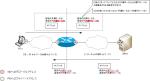
本社と支社間の通信を行うためのサイトツーサイトIPSec-VPNの設定を行います。IPSec VTI(Virtual Tunnel Interface)によるルートベースのIPSec-VPNの設定です。
ネットワーク構成
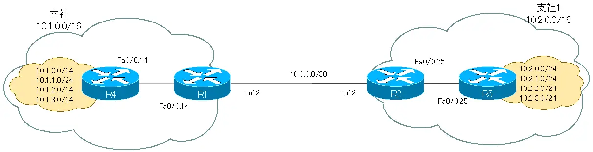
![図 [演習]サイトツーサイトIPSec-VPN ネットワーク構成](https://www.n-study.com/wp-content/uploads/2023/04/site-to-site-ipsec-vpn-crypto-map-exercises-01.png)
設定条件
- IPSecによる暗号化通信を行うVPNゲートウェイは、R1、R2です。R4、R5は各拠点の内部ルータです。内部ネットワークのルーティングとして、EIGRPを利用します。
- IPSec VPNによって本社と支社1を接続して拠点間の通信ができるように設定します。
- IPSec VPNの設定は、VTIを利用します。R1-R2間をポイントツーポイントトンネルiインタフェースで接続して、トンネルインタフェース経由のパケットを暗号化します。
- 拠点内からインターネットへの接続を可能にします。
初期設定
各ルータには、次の設定を行っています。
- ホスト名
- IPアドレス
R1 Initical Configuration(Click)
!
!
!
version 12.4
service timestamps debug datetime msec
service timestamps log datetime msec
no service password-encryption
!
hostname R1
!
boot-start-marker
boot-end-marker
!
!
no aaa new-model
memory-size iomem 5
!
!
ip cef
!
!
ip auth-proxy max-nodata-conns 3
ip admission max-nodata-conns 3
!
!
!
!
!
!
!
!
!
!
!
!
!
!
!
!
!
!
!
!
!
!
interface FastEthernet0/0
 no ip address
 duplex auto
 speed auto
!
interface FastEthernet0/0.1
 encapsulation dot1Q 1 native
 ip address 1.1.1.1 255.255.255.0
 ip virtual-reassembly
!
interface FastEthernet0/0.14
 encapsulation dot1Q 14
 ip address 10.1.14.1 255.255.255.0
 ip virtual-reassembly
!
ip http server
no ip http secure-server
!
ip forward-protocol nd
!
!
!
!
!
control-plane
!
!
!
!
!
!
!
!
!
!
line con 0
 privilege level 15

line aux 0
line vty 0 4
 login
!
!
end
R2 Initical Configuration(Click)
!
!
!
version 12.4
service timestamps debug datetime msec
service timestamps log datetime msec
no service password-encryption
!
hostname R2
!
boot-start-marker
boot-end-marker
!
!
no aaa new-model
memory-size iomem 5
!
!
ip cef
!
!
ip auth-proxy max-nodata-conns 3
ip admission max-nodata-conns 3
!
!
!
!
!
!
!
!
!
!
!
!
!
!
!
!
!
!
!
!
!
!
interface FastEthernet0/0
 no ip address
 duplex auto
 speed auto
!
interface FastEthernet0/0.1
 encapsulation dot1Q 2
 ip address 2.2.2.2 255.255.255.0
 ip virtual-reassembly
!
interface FastEthernet0/0.25
 encapsulation dot1Q 25
 ip address 10.2.25.2 255.255.255.0
!
ip http server
no ip http secure-server
!
ip forward-protocol nd
!
!
!
!
!
control-plane
!
!
!
!
!
!
!
!
!
!
line con 0
  privilege level 15

line aux 0
line vty 0 4
 login
!
!
end
R4 Initical Configuration(Click)
!
!
!
version 12.4
service timestamps debug datetime msec
service timestamps log datetime msec
no service password-encryption
!
hostname R4
!
boot-start-marker
boot-end-marker
!
!
no aaa new-model
memory-size iomem 5
!
!
ip cef
!
!
ip auth-proxy max-nodata-conns 3
ip admission max-nodata-conns 3
!
!
!
!
!
!
!
!
!
!
!
!
!
!
!
!
!
!
!
!
!
!
interface Loopback0
 ip address 10.1.1.4 255.255.255.0 secondary
 ip address 10.1.2.4 255.255.255.0 secondary
 ip address 10.1.3.4 255.255.255.0 secondary
 ip address 10.1.0.4 255.255.255.0
!
interface FastEthernet0/0
 no ip address
 duplex auto
 speed auto
!
interface FastEthernet0/0.14
 encapsulation dot1Q 14
 ip address 10.1.14.4 255.255.255.0
!
ip http server
no ip http secure-server
!
ip forward-protocol nd
!
!
!
!
!
control-plane
!
!
!
!
!
!
!
!
!
!
line con 0
 privilege level 15
line aux 0
line vty 0 4
 login
!
!
end
R5 Initical Configuration(Click)
!
!
!
version 12.4
service timestamps debug datetime msec
service timestamps log datetime msec
no service password-encryption
!
hostname R5
!
boot-start-marker
boot-end-marker
!
!
no aaa new-model
memory-size iomem 5
!
!
ip cef
!
!
ip auth-proxy max-nodata-conns 3
ip admission max-nodata-conns 3
!
!
!
!
!
!
!
!
!
!
!
!
!
!
!
!
!
!
!
!
!
!
interface Loopback0
 ip address 10.2.1.5 255.255.255.0 secondary
 ip address 10.2.2.5 255.255.255.0 secondary
 ip address 10.2.3.5 255.255.255.0 secondary
 ip address 10.2.0.5 255.255.255.0
!
interface FastEthernet0/0
 no ip address
 duplex auto
 speed auto
!
interface FastEthernet0/0.25
 encapsulation dot1Q 25
 ip address 10.2.25.5 255.255.255.0
!
ip http server
no ip http secure-server
!
ip forward-protocol nd
!
!
!
!
!
control-plane
!
!
!
!
!
!
!
!
!
!
line con 0
 privilege level 15
line aux 0
line vty 0 4
 login
!
!
end
ISP Initical Configuration(Click)
!
!
ersion 12.4
service timestamps debug datetime msec
service timestamps log datetime msec
no service password-encryption
!
hostname ISP
!
boot-start-marker
boot-end-marker
!
!
no aaa new-model
memory-size iomem 5
!
!
ip cef
!
!
ip auth-proxy max-nodata-conns 3
ip admission max-nodata-conns 3
!
!
!
!
!
!
!
!
!
!
!
!
!
!
!
!
!
!
!
!
!
!
interface Loopback0
 ip address 100.1.1.10 255.255.255.0 secondary
 ip address 100.1.2.10 255.255.255.0 secondary
 ip address 100.1.3.10 255.255.255.0 secondary
 ip address 100.1.0.10 255.255.255.0
!
interface FastEthernet0/0
 no ip address
 duplex auto
 speed auto
!
interface FastEthernet0/0.1
 encapsulation dot1Q 1 native
 ip address 1.1.1.10 255.255.255.0
!
interface FastEthernet0/0.2
 encapsulation dot1Q 2
 ip address 2.2.2.10 255.255.255.0
!
interface FastEthernet0/0.3
 encapsulation dot1Q 3
 ip address 3.3.3.10 255.255.255.0
!
ip http server
no ip http secure-server
!
ip forward-protocol nd
!
!
!
!
!
control-plane
!
!
!
!
!
!
!
!
!
!
line con 0
 privilege level 15
line aux 0
line vty 0 4
 login
!
!
end
設定・確認
Step1:トンネルインタフェースの設定
R1-R2間でトンネルインタフェースによって、仮想的にポイントツーポイント接続します。トンネルインタフェースのカプセル化は、ひとまずデフォルトのGREとします。
トンネルインタフェースは内部ネットワークの一部になるため、以下のプライベートアドレスを設定します。
R1 Tunnel12:10.0.0.1/30
R2 Tunnel12:10.0.0.2/30
また、tunnel destinationで指定するIPアドレスへ到達できるようにするために、デフォルトルートを設定します。
R1 トンネルインタフェースの設定
interface Tunnel12
 ip address 10.0.0.1 255.255.255.252
 tunnel source 1.1.1.1
 tunnel destination 2.2.2.2
!
ip route 0.0.0.0 0.0.0.0 1.1.1.10
R2 トンネルインタフェースの設定
interface Tunnel12
 ip address 10.0.0.2 255.255.255.252
 tunnel source 2.2.2.2
 tunnel destination 1.1.1.1
!
ip route 0.0.0.0 0.0.0.0 2.2.2.10
Step2:トンネルインタフェースの確認
R1-R2間のトンネルインタフェースを確認します。show interface tunnel12でトンネルインタフェースがup/upであることを確認します。また、Pingでトンネルの対向のIPアドレスへ通信できることを確認します。
R1 トンネルインタフェースの確認
R1#show interfaces tunnel 12
Tunnel12 is up, line protocol is up
  Hardware is Tunnel
  Internet address is 10.0.0.1/30
  MTU 1514 bytes, BW 9 Kbit/sec, DLY 500000 usec,
     reliability 255/255, txload 1/255, rxload 1/255
  Encapsulation TUNNEL, loopback not set
  Keepalive not set
  Tunnel source 1.1.1.1, destination 2.2.2.2
  Tunnel protocol/transport GRE/IP
    Key disabled, sequencing disabled
    Checksumming of packets disabled
  Tunnel TTL 255
-- omitted --
R1#ping 10.0.0.2 source tunnel 12

Type escape sequence to abort.
Sending 5, 100-byte ICMP Echos to 10.0.0.2, timeout is 2 seconds:
Packet sent with a source address of 10.0.0.1
!!!!!
Success rate is 100 percent (5/5), round-trip min/avg/max = 88/92/96 ms
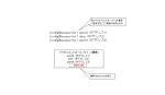
R1-R2間のトンネルインタフェースによって、本社と支社1のネットワークは以下のように接続されていることになります。
Step3:内部ネットワークのルーティングの設定
R1/R2/R4/R5でEIGRPを利用して、内部ネットワークのルーティングを行うように設定します。EIGRPのAS番号は1として設定します。また、R1とR2では拠点内のルート情報を集約します。
R1 内部ネットワークのルーティング(EIGRP)の設定
interface Tunnel12
 ip summary-address eigrp 1 10.1.0.0 255.255.0.0 5
!
router eigrp 1
 network 10.0.0.0
 no auto-summary
R2 内部ネットワークのルーティング(EIGRP)の設定
interface Tunnel12
 ip summary-address eigrp 1 10.2.0.0 255.255.0.0 5
!
router eigrp 1
 network 10.0.0.0
 no auto-summary
R4 内部ネットワークのルーティング(EIGRP)の設定
router eigrp 1
 network 10.0.0.0
 no auto-summary
R5 内部ネットワークのルーティング(EIGRP)の設定
router eigrp 1
 network 10.0.0.0
 no auto-summary
Step4:内部ネットワークのルーティングの確認
以下のshowコマンドでEIGRPによって、内部ネットワークのルート情報を各ルータのルーティングテーブルに正しく登録できていることを確認します。
- show ip eigrp interface
- show ip eigrp neighbor
- show ip route eigrp
R1では、次のような表示になります。
R1 内部ネットワークのルーティング(EIGRP)の確認
R1#show ip eigrp interfaces
IP-EIGRP interfaces for process 1
                        Xmit Queue   Mean   Pacing Time   Multicast    Pending
Interface        Peers  Un/Reliable  SRTT   Un/Reliable   Flow Timer   Routes
Fa0/0.14           1        0/0        72       0/1          272           0
Tu12               1        0/0       114      71/2659      3115           0
R1#show ip eigrp neighbors
IP-EIGRP neighbors for process 1
H   Address                 Interface       Hold Uptime   SRTT   RTO  Q  Seq
                                            (sec)         (ms)       Cnt Num
1   10.1.14.4               Fa0/0.14           9 00:02:25   72   432  0  5
0   10.0.0.2                Tu12              12 00:02:45  114  5000  0  3
R1#show ip route eigrp
     10.0.0.0/8 is variably subnetted, 8 subnets, 3 masks
D       10.2.0.0/16 [90/297246976] via 10.0.0.2, 00:02:47, Tunnel12
D       10.1.3.0/24 [90/156160] via 10.1.14.4, 00:02:26, FastEthernet0/0.14
D       10.1.2.0/24 [90/156160] via 10.1.14.4, 00:02:26, FastEthernet0/0.14
D       10.1.1.0/24 [90/156160] via 10.1.14.4, 00:02:26, FastEthernet0/0.14
D       10.1.0.0/24 [90/156160] via 10.1.14.4, 00:02:26, FastEthernet0/0.14
D       10.1.0.0/16 is a summary, 00:04:02, Null0
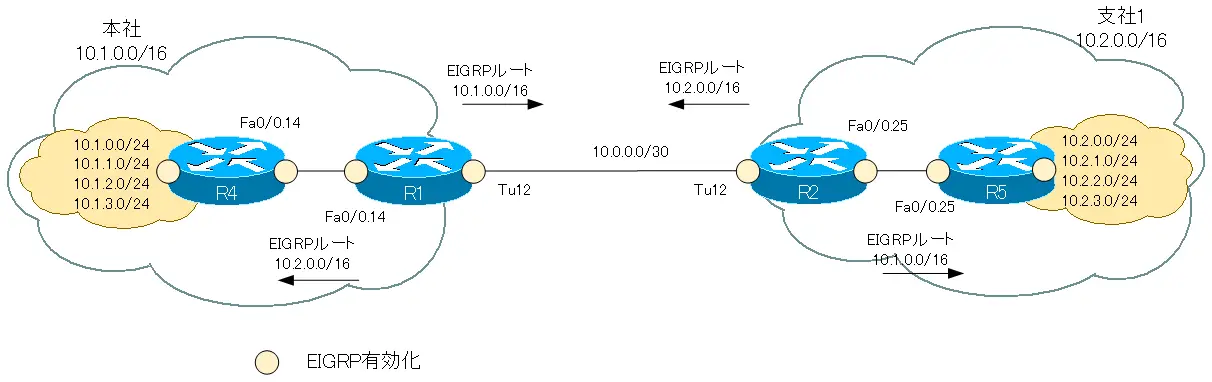
図では、R4/R5がアドバタイズするEIGRPルートは省略しています。
Step5:IPSec暗号化の設定(VTI)
R1-R2間のトンネルインタフェースで送受信するパケットをIPSecで暗号化します。
crypto isakmp policyで対向となるVPNゲートウェイを設定します。
R1 ISAKMPポリシーの設定
crypto isakmp policy 1
 authentication pre-share
crypto isakmp key cisco address 2.2.2.2
R2 ISAKMPポリシーの設定
crypto isakmp policy 1
 authentication pre-share
crypto isakmp key cisco address 1.1.1.1
セキュリティプロトコル、暗号化アルゴリズム、ハッシュアルゴリズム、モードをIPSecトランスフォームセットとして設定します。設定内容を次の表にまとめています。
| トランスフォームセット名 | IPSEC |
| セキュリティプロトコル | ESP |
| 暗号化アルゴリズム | 3DES |
| 認証アルゴリズム | SHA-1 |
| モード | トンネルモード |
R1、R2の設定は共通で、次のように行います。
R1/R2 IPSecトランスフォームセットの設定
crypto ipsec transform-set IPSEC esp-3des esp-sha-hmac
そして、IPSecプロファイルを作成します。IPSecプロファイルにはトランスフォームセットを関連付けます。
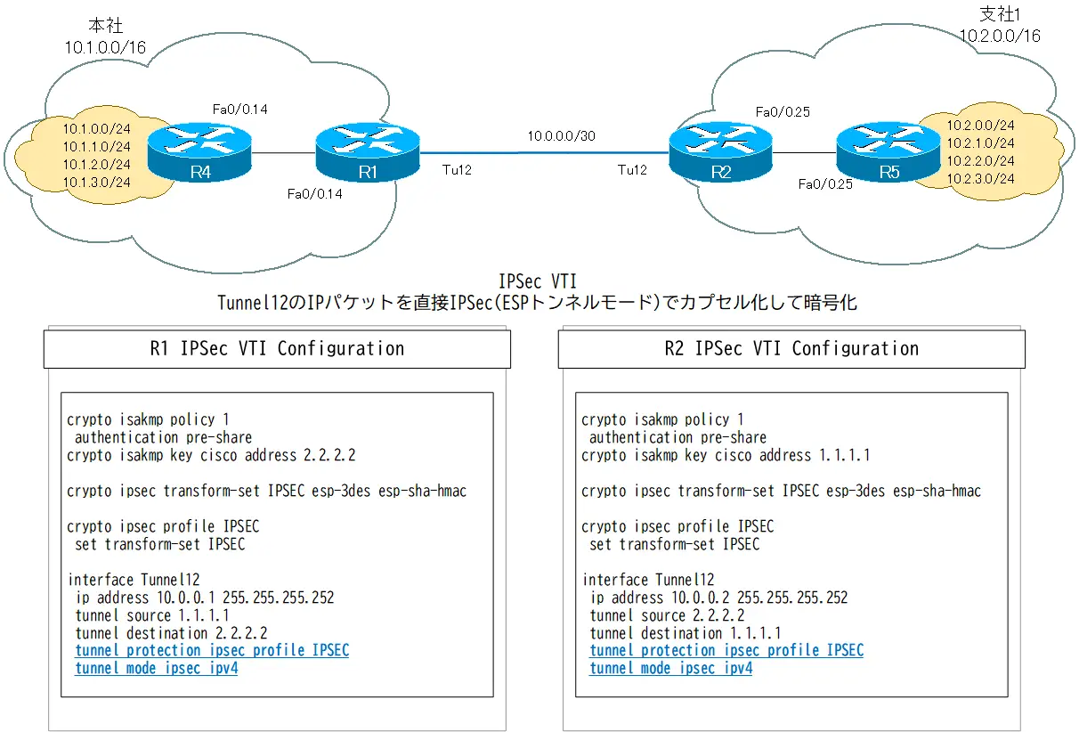
最後にTunnel12にIPSecプロファイルを適用します。tunnel protectionコマンドでTunnel12インタフェースにIPSecプロファイルを適用します。また、カプセル化をデフォルトのGREからipsec ipv4とします。
R1/R2 IPSec VTIの設定
crypto ipsec profile IPSEC
 set transform-set IPSEC
!
interface Tunnel12
 tunnel protection ipsec profile IPSEC
 tunnel mode ipsec ipv4
Step6:VTIの確認
R1-R2間のトンネルインタフェースの状態を確認します。
R1 show interface tunnel
R1#show interfaces tunnel 12
Tunnel12 is up, line protocol is up
  Hardware is Tunnel
  Internet address is 10.0.0.1/30
  MTU 1514 bytes, BW 9 Kbit/sec, DLY 500000 usec,
     reliability 255/255, txload 1/255, rxload 1/255
  Encapsulation TUNNEL, loopback not set
  Keepalive not set
  Tunnel source 1.1.1.1, destination 2.2.2.2
  Tunnel protocol/transport IPSEC/IP
  Tunnel TTL 255
  Fast tunneling enabled
  Tunnel transmit bandwidth 8000 (kbps)
  Tunnel receive bandwidth 8000 (kbps)
  Tunnel protection via IPSec (profile "IPSEC")
-- omitted --
トンネルインタフェースに適用しているIPSecプロファイルを確認するためにshow crypo ipsec profileおよびshow crypto ipsec transform-setコマンドを利用します。
R1 show crypto ipsec profile/show crypto ipsec transform-set
R1#show crypto ipsec profile
IPSEC profile IPSEC
        Security association lifetime: 4608000 kilobytes/3600 seconds
        PFS (Y/N): N
        Transform sets={
                IPSEC,
        }

R1#show crypto ipsec transform-set
Transform set IPSEC: { esp-3des esp-sha-hmac  }
   will negotiate = { Tunnel,  },
IPSec VTIでR1-R2間のトンネルインタフェースのパケットをすべて暗号化しています。トンネルインタフェースでEIGRPを有効にしているので、定期的にHelloパケットが流れます。そのため、VPNゲートウェイR1-R2間で常時SAが確立されてることになります。
ISAKMP SAを確認するには、show crypto isakmp saコマンドを利用します。
R1 show crypto isakmp sa
R1#show crypto isakmp sa
dst             src             state          conn-id slot status
1.1.1.1         2.2.2.2         QM_IDLE              1    0 ACTIVE
また、IPSec SAはshow crypto ipsec saコマンドで確認します。
R1 show crypto ipsec sa
R1#show crypto ipsec sa

interface: Tunnel12
    Crypto map tag: Tunnel12-head-0, local addr 1.1.1.1

   protected vrf: (none)
   local  ident (addr/mask/prot/port): (1.1.1.1/255.255.255.255/47/0)
   remote ident (addr/mask/prot/port): (2.2.2.2/255.255.255.255/47/0)
   current_peer 2.2.2.2 port 500
     PERMIT, flags={origin_is_acl,}
    #pkts encaps: 70, #pkts encrypt: 70, #pkts digest: 70
    #pkts decaps: 69, #pkts decrypt: 69, #pkts verify: 69
    #pkts compressed: 0, #pkts decompressed: 0
    #pkts not compressed: 0, #pkts compr. failed: 0
    #pkts not decompressed: 0, #pkts decompress failed: 0
    #send errors 145, #recv errors 0

     local crypto endpt.: 1.1.1.1, remote crypto endpt.: 2.2.2.2
     path mtu 1500, ip mtu 1500, ip mtu idb FastEthernet0/0.1
     current outbound spi: 0x41FFF956(1107294550)

     inbound esp sas:
      spi: 0x54577010(1415016464)
        transform: esp-3des esp-sha-hmac ,
        in use settings ={Transport, }
        conn id: 2001, flow_id: SW:1, crypto map: Tunnel12-head-0
        sa timing: remaining key lifetime (k/sec): (4431019/3333)
        IV size: 8 bytes
        replay detection support: Y
        Status: ACTIVE

     inbound ah sas:

     inbound pcp sas:

     outbound esp sas:
      spi: 0x41FFF956(1107294550)
        transform: esp-3des esp-sha-hmac ,
        in use settings ={Transport, }
        conn id: 2002, flow_id: SW:2, crypto map: Tunnel12-head-0
        sa timing: remaining key lifetime (k/sec): (4431019/3328)
        IV size: 8 bytes
        replay detection support: Y
        Status: ACTIVE

     outbound ah sas:

     outbound pcp sas:
Step7:拠点間の通信の確認
R4から支社1宛てにPingを行います。
R4から支社1への通信
R4#ping 10.2.1.5

Type escape sequence to abort.
Sending 5, 100-byte ICMP Echos to 10.2.1.5, timeout is 2 seconds:
!!!!!
Success rate is 100 percent (5/5), round-trip min/avg/max = 16/16/16 ms
R4から支社1への通信が正常に行われていることがわかります。
Step7:インターネット宛てのルーティングの設定
通常のインターネットアクセスを行うためのルーティングについて設定します。R1/R2では、Step1でGREトンネルインタフェースを作成するときに、インターネットへルーティングするためのデフォルトルートを設定済みです。R1/R2のデフォルトルートをEIGRPでR4/R5にアドバタイズするために、スタティックルートをEIGRPに再配送します。
R1/R2 デフォルトルートのアドバタイズ
router eigrp 1
 redistribute static
R4/R5のルーティングテーブルにデフォルトルートが登録されますが、それだけではインターネット宛ての通信はできません。さらにNATのアドレス変換が必要です。
R4 show ip route eigrp
R4#show ip route eigrp
     10.0.0.0/8 is variably subnetted, 7 subnets, 3 masks
D       10.2.0.0/16 [90/297249536] via 10.1.14.1, 00:07:12, FastEthernet0/0.14
D       10.0.0.0/30 [90/297246976] via 10.1.14.1, 00:24:41, FastEthernet0/0.14
D*EX 0.0.0.0/0 [170/30720] via 10.1.14.1, 00:01:43, FastEthernet0/0.14
R4#ping 100.1.0.10

Type escape sequence to abort.
Sending 5, 100-byte ICMP Echos to 100.1.0.10, timeout is 2 seconds:
.....
Success rate is 0 percent (0/5)
Step8:NATの設定
内部ネットワークのプライベートアドレスからインターネットへの通信ができるようにするには、R1/R2でNATを行います。内部グローバルアドレスは、R1/R2のISPと接続しているインタフェースを利用します。
| ルータ | 内部ネットワーク | 外部ネットワーク |
| R1 | Fa0/0.14 | Fa0/0.1 |
| R2 | Fa0/0.25 | Fa0/0.1 |
R1 NATの設定
interface FastEthernet0/0.1
 ip nat outside
!
interface FastEthernet0/0.14
 ip nat inside
!
ip nat inside source list 1 interface FastEthernet0/0.1 overload
!
access-list 1 permit 10.1.0.0 0.0.255.255
R2 NATの設定
interface FastEthernet0/0.1
 ip nat outside
!
interface FastEthernet0/0.25
 ip nat inside
!
ip nat inside source list 1 interface FastEthernet0/0.1 overload
!
access-list 1 permit 10.2.0.0 0.0.255.255
なお、トンネルインタフェース(Tunne12)はNATの内部ネットワークにしていません。そのため、内部ネットワークのIPパケットはNAT変換されません。crypto mapでの設定のときのように、内部ネットワークのIPパケットをNAT変換対象から除外する設定は不要です。
Step9:ACLの設定
R1/R2のインターネット側のインタフェースにACLを適用します。インバウンドのACLで対向のVPNゲートウェイとの間のESPとIKEをpermitします。また、各拠点の内部ネットワークとインターネットの通信を可能にするためのリフレクシブアクセスリストの設定も行います。
R1 ACLの設定
ip access-list extended INBOUND
  evaluate ref-acl
  permit esp 2.2.2.2 0.0.0.0 1.1.1.1 0.0.0.0
  permit udp 2.2.2.2 0.0.0.0 1.1.1.1 0.0.0.0 eq isakmp
!
ip access-list extended OUTBOUND
  permit ip any any reflect ref-acl
!
interface FastEthernet0/0.1
  ip access-group INBOUND in
  ip access-group OUTBOUND out
R2 ACLの設定
ip access-list extended INBOUND
  evaluate ref-acl
  permit esp 1.1.1.1 0.0.0.0 2.2.2.2 0.0.0.0
  permit udp 1.1.1.1 0.0.0.0 2.2.2.2 0.0.0.0 eq isakmp
!
ip access-list extended OUTBOUND
  permit ip any any reflect ref-acl
!
interface FastEthernet0/0.1
  ip access-group INBOUND in
  ip access-group OUTBOUND out
Step10:インターネット宛ての通信の確認
R4からインターネットを想定している100.1.1.10へPingを行います。
R4からインターネットへの通信
R4#ping 100.1.1.10

Type escape sequence to abort.
Sending 5, 100-byte ICMP Echos to 100.1.1.10, timeout is 2 seconds:
!!!!!
Success rate is 100 percent (5/5), round-trip min/avg/max = 4/6/8 ms
R4からインターネットへ正常に通信ができていることが確認できます。このときR1でのNATテーブルは次のようになります。
R1 show ip nat translatons(NATテーブル)
R1#show ip nat translations
Pro Inside global      Inside local       Outside local      Outside global
icmp 1.1.1.1:10        10.1.14.4:10       100.1.0.10:10      100.1.0.10:10
icmp 1.1.1.1:11        10.1.14.4:11       100.1.0.10:11      100.1.0.10:11
また、このとき内部ネットワークからインターネット宛ての戻りをpermitするリフレクシブアクセスリストが自動的に作成されています。自動作成されたリフレクシブアクセスリストのエントリは、show access-listで確認できます。R1では、次のようなリフレクシブアクセスリストのエントリが作成されます。
R1 show access-list
R1#show access-lists
Standard IP access list 1
    10 permit 10.1.0.0, wildcard bits 0.0.255.255 (2 matches)
Extended IP access list INBOUND
    10 evaluate ref-acl
    20 permit esp host 2.2.2.2 host 1.1.1.1 (51 matches)
    30 permit udp host 2.2.2.2 host 1.1.1.1 eq isakmp
Extended IP access list OUTBOUND
    10 permit ip any any reflect ref-acl (27 matches)
Reflexive IP access list ref-acl
     permit icmp host 100.1.1.10 host 1.1.1.1  (20 matches) (time left 297)
     permit icmp host 100.1.1.10 host 10.1.14.4  (15 matches) (time left 161)
完了した設定ファイル
R1 Completed Configuration(Click)
!

!
version 12.4
service timestamps debug datetime msec
service timestamps log datetime msec
no service password-encryption
!
hostname R1
!
boot-start-marker
boot-end-marker
!
!
no aaa new-model
memory-size iomem 5
!
!
ip cef
!
!
ip auth-proxy max-nodata-conns 3
ip admission max-nodata-conns 3
!
!
!
!
!
!
!
!
!
!
!
!
!
!
!
!
!
!
!
crypto isakmp policy 1
 authentication pre-share
crypto isakmp key cisco address 2.2.2.2
!
!
crypto ipsec transform-set IPSEC esp-3des esp-sha-hmac
!
crypto ipsec profile IPSEC
 set transform-set IPSEC
!
!
!
!
!
interface Tunnel12
 ip address 10.0.0.1 255.255.255.252
 ip summary-address eigrp 1 10.1.0.0 255.255.0.0 5
 tunnel source 1.1.1.1
 tunnel destination 2.2.2.2
 tunnel mode ipsec ipv4
 tunnel protection ipsec profile IPSEC
!
interface FastEthernet0/0
 no ip address
 duplex auto
 speed auto
!
interface FastEthernet0/0.1
 encapsulation dot1Q 1 native
 ip address 1.1.1.1 255.255.255.0
 ip access-group INBOUND in
 ip access-group OUTBOUND out
 ip nat outside
 ip virtual-reassembly
!
interface FastEthernet0/0.14
 encapsulation dot1Q 14
 ip address 10.1.14.1 255.255.255.0
 ip nat inside
 ip virtual-reassembly
!
interface FastEthernet1/0
 no ip address
 shutdown
 duplex auto
 speed auto
!
router eigrp 1
 redistribute static
 network 10.0.0.0
 no auto-summary
!
ip http server
no ip http secure-server
!
ip forward-protocol nd
ip route 0.0.0.0 0.0.0.0 1.1.1.10
!
ip nat inside source list 1 interface FastEthernet0/0.1 overload
!
!
ip access-list extended INBOUND
 evaluate ref-acl
 permit esp host 2.2.2.2 host 1.1.1.1
 permit udp host 2.2.2.2 host 1.1.1.1 eq isakmp
ip access-list extended OUTBOUND
 permit ip any any reflect ref-acl
access-list 1 permit 10.1.0.0 0.0.255.255
!
!
!
control-plane
!
!
!
!
!
!
!
!
!
!
line con 0
 privilege level 15
line aux 0
line vty 0 4
 login
!
!
end
R2 Completed Configuration(Click)
!

!
version 12.4
service timestamps debug datetime msec
service timestamps log datetime msec
no service password-encryption
!
hostname R2
!
boot-start-marker
boot-end-marker
!
!
no aaa new-model
memory-size iomem 5
!
!
ip cef
!
!
ip auth-proxy max-nodata-conns 3
ip admission max-nodata-conns 3
!
!
!
!
!
!
!
!
!
!
!
!
!
!
!
!
!
!
!
crypto isakmp policy 1
 authentication pre-share
crypto isakmp key cisco address 1.1.1.1
!
!
crypto ipsec transform-set IPSEC esp-3des esp-sha-hmac
!
crypto ipsec profile IPSEC
 set transform-set IPSEC
!
!
!
!
!
interface Tunnel12
 ip address 10.0.0.2 255.255.255.252
 ip summary-address eigrp 1 10.2.0.0 255.255.0.0 5
 tunnel source 2.2.2.2
 tunnel destination 1.1.1.1
 tunnel mode ipsec ipv4
 tunnel protection ipsec profile IPSEC
!
interface FastEthernet0/0
 no ip address
 duplex auto
 speed auto
!
interface FastEthernet0/0.1
 encapsulation dot1Q 2
 ip address 2.2.2.2 255.255.255.0
 ip access-group INBOUND in
 ip access-group OUTBOUND out
 ip nat outside
 ip virtual-reassembly
!
interface FastEthernet0/0.25
 encapsulation dot1Q 25
 ip address 10.2.25.2 255.255.255.0
 ip nat inside
 ip virtual-reassembly
!
interface FastEthernet1/0
 no ip address
 shutdown
 duplex auto
 speed auto
!
router eigrp 1
 redistribute static
 network 10.0.0.0
 no auto-summary
!
ip http server
no ip http secure-server
!
ip forward-protocol nd
ip route 0.0.0.0 0.0.0.0 2.2.2.10
!
ip nat inside source list 1 interface FastEthernet0/0.1 overload
!
!
ip access-list extended INBOUND
 evaluate ref-acl
 permit esp host 1.1.1.1 host 2.2.2.2
 permit udp host 1.1.1.1 host 2.2.2.2 eq isakmp
ip access-list extended OUTBOUND
 permit ip any any reflect ref-acl
access-list 1 permit 10.2.0.0 0.0.255.255
!
!
!
control-plane
!
!
!
!
!
!
!
!
!
!
line con 0
 privilege level 15
line aux 0
line vty 0 4
 login
!
!
end
R4 Completed Configuration(Click)
!

!
version 12.4
service timestamps debug datetime msec
service timestamps log datetime msec
no service password-encryption
!
hostname R4
!
boot-start-marker
boot-end-marker
!
!
no aaa new-model
memory-size iomem 5
!
!
ip cef
!
!
ip auth-proxy max-nodata-conns 3
ip admission max-nodata-conns 3
!
!
!
!
!
!
!
!
!
!
!
!
!
!
!
!
!
!
!
!
!
!
interface Loopback0
 ip address 10.1.1.4 255.255.255.0 secondary
 ip address 10.1.2.4 255.255.255.0 secondary
 ip address 10.1.3.4 255.255.255.0 secondary
 ip address 10.1.0.4 255.255.255.0
!
interface FastEthernet0/0
 no ip address
 duplex auto
 speed auto
!
interface FastEthernet0/0.14
 encapsulation dot1Q 14
 ip address 10.1.14.4 255.255.255.0
!
interface FastEthernet1/0
 no ip address
 shutdown
 duplex auto
 speed auto
!
router eigrp 1
 network 10.0.0.0
 no auto-summary
!
ip http server
no ip http secure-server
!
ip forward-protocol nd
!
!
!
!
!
control-plane
!
!
!
!
!
!
!
!
!
!
line con 0
 privilege level 15
line aux 0
line vty 0 4
 login
!
!
end
R5 Completed Configuration(Click)
!

!
version 12.4
service timestamps debug datetime msec
service timestamps log datetime msec
no service password-encryption
!
hostname R5
!
boot-start-marker
boot-end-marker
!
!
no aaa new-model
memory-size iomem 5
!
!
ip cef
!
!
ip auth-proxy max-nodata-conns 3
ip admission max-nodata-conns 3
!
!
!
!
!
!
!
!
!
!
!
!
!
!
!
!
!
!
!
!
!
!
interface Loopback0
 ip address 10.2.1.5 255.255.255.0 secondary
 ip address 10.2.2.5 255.255.255.0 secondary
 ip address 10.2.3.5 255.255.255.0 secondary
 ip address 10.2.0.5 255.255.255.0
!
interface FastEthernet0/0
 no ip address
 duplex auto
 speed auto
!
interface FastEthernet0/0.25
 encapsulation dot1Q 25
 ip address 10.2.25.5 255.255.255.0
!
interface FastEthernet1/0
 no ip address
 shutdown
 duplex auto
 speed auto
!
router eigrp 1
 network 10.0.0.0
 no auto-summary
!
ip http server
no ip http secure-server
!
ip forward-protocol nd
!
!
!
!
!
control-plane
!
!
!
!
!
!
!
!
!
!
line con 0
 privilege level 15
line aux 0
line vty 0 4
 login
!
!
end
ISP Completed Configuration(Click)
!
!
!
ersion 12.4
service timestamps debug datetime msec
service timestamps log datetime msec
no service password-encryption
!
hostname ISP
!
boot-start-marker
boot-end-marker
!
!
no aaa new-model
memory-size iomem 5
!
!
ip cef
!
!
ip auth-proxy max-nodata-conns 3
ip admission max-nodata-conns 3
!
!
!
!
!
!
!
!
!
!
!
!
!
!
!
!
!
!
!
!
!
!
interface Loopback0
 ip address 100.1.1.10 255.255.255.0 secondary
 ip address 100.1.2.10 255.255.255.0 secondary
 ip address 100.1.3.10 255.255.255.0 secondary
 ip address 100.1.0.10 255.255.255.0
!
interface FastEthernet0/0
 no ip address
 duplex auto
 speed auto
!
interface FastEthernet0/0.1
 encapsulation dot1Q 1 native
 ip address 1.1.1.10 255.255.255.0
!
interface FastEthernet0/0.2
 encapsulation dot1Q 2
 ip address 2.2.2.10 255.255.255.0
!
interface FastEthernet0/0.3
 encapsulation dot1Q 3
 ip address 3.3.3.10 255.255.255.0
!
ip http server
no ip http secure-server
!
ip forward-protocol nd
!
!
!
!
!
control-plane
!
!
!
!
!
!
!
!
!
!
line con 0
 privilege level 15
line aux 0
line vty 0 4
 login
!
!
end
関連記事
関連記事


インターネットVPN
- インターネットVPNの概要
- インターネットへの接続形態
- VPNサービスとは?
- NordVPN ~セキュアなVPNサービスを手軽に利用しよう~
- IPSecの概要
- IKE ~SAの生成と管理~
- IPSec サイト間VPNの動作
- IPSec サイト間VPNの設定 ~crypto mapによる設定~
- IPSec サイト間VPNの設定例
- [演習]サイトツーサイトIPSec-VPN(crypto map)
- [演習]サイトツーサイトIPSec-VPN(VTI)
- [演習]サイトツーサイトIPSec-VPN(VTI) トラブルシューティング
- IPSec 設定ミスの切り分けと修正 Part1
- IPSec 設定ミスの切り分けと修正 Part2
- IPSec 設定ミスの切り分けと修正 Part3
- DMVPNの設定例
- DMVPN設定演習[Cisco] NHRP Phase1
- DMVPN設定演習[Cisco] NHRP Phase2
- DMVPN設定演習[Cisco] NHRP Phase3
- SSL-VPNの実現方式
- SSL-VPN(クライアントレス)の設定例 (Cisco)
