目次
概要
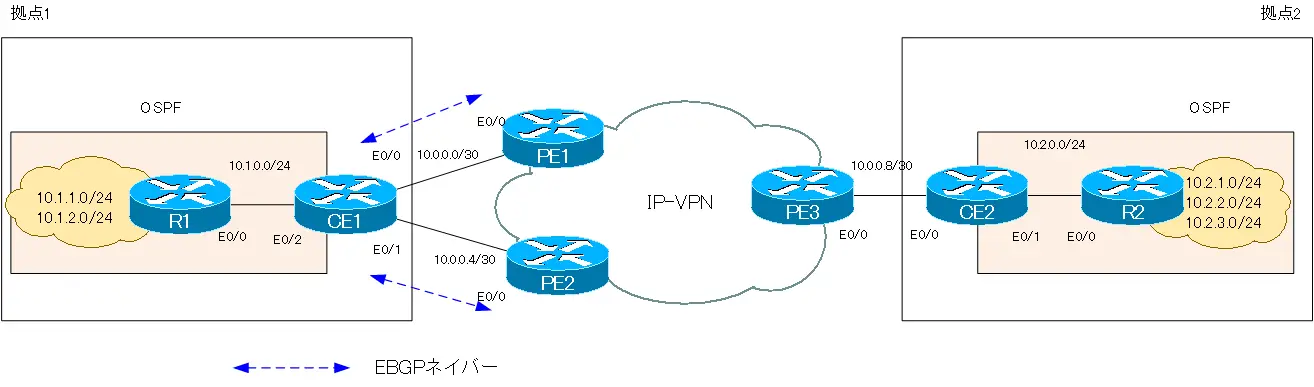
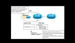
IP-VPN(MPLS-VPN)で、PE-CE間のルーティングプロトコルとしてBGPを利用するときの設定例です。CEルータ側のBGPの設定に注目しています。
ネットワーク構成
初期設定
PE1/PE2
PE1/PE2は、IP-VPN網内のOSPFとMPLSのラベルスイッチングの設定を行っています。また、PE間のフルメッシュMP-BGPネイバーを確立しています。そして、CE1との間でVRF「VPN」におけるBGPネイバーを確立しています。
PE1 Initial Configuration(Click)
hostname PE1
!
ip vrf VPN
 rd 1:100
 route-target export 1:100
 route-target import 1:100
!
interface Loopback0
 ip address 192.168.0.1 255.255.255.255
!
interface Ethernet0/0
 ip vrf forwarding VPN
 ip address 10.0.0.1 255.255.255.252
!
interface Ethernet0/1
 ip address 192.168.1.1 255.255.255.0
 mpls ip
!
router ospf 1
 log-adjacency-changes
 network 192.168.0.0 0.0.255.255 area 0
!
router bgp 1
 no synchronization
 bgp log-neighbor-changes
 neighbor 192.168.0.2 remote-as 1
 neighbor 192.168.0.2 update-source Loopback0
 neighbor 192.168.0.2 next-hop-self
 neighbor 192.168.0.3 remote-as 1
 neighbor 192.168.0.3 update-source Loopback0
 neighbor 192.168.0.3 next-hop-self
 no auto-summary
 !
 address-family vpnv4
  neighbor 192.168.0.2 activate
  neighbor 192.168.0.2 send-community extended
  neighbor 192.168.0.3 activate
  neighbor 192.168.0.3 send-community extended
 exit-address-family
 !
 address-family ipv4 vrf VPN
  neighbor 10.0.0.2 remote-as 100
  neighbor 10.0.0.2 activate
  no synchronization
  network 10.0.0.0 mask 255.255.255.252
 exit-address-family
PE2 Initial Configuration(Click)
hostname PE2
!
ip vrf VPN
 rd 1:100
 route-target export 1:100
 route-target import 1:100
!
interface Loopback0
 ip address 192.168.0.2 255.255.255.255
!
interface Ethernet0/0
 ip vrf forwarding VPN
 ip address 10.0.0.5 255.255.255.252
!
interface Ethernet0/1
 ip address 192.168.1.2 255.255.255.0
 mpls ip
!
router ospf 1
 log-adjacency-changes
 network 192.168.0.0 0.0.255.255 area 0
!
router bgp 1
 no synchronization
 bgp log-neighbor-changes
 neighbor 192.168.0.1 remote-as 1
 neighbor 192.168.0.1 update-source Loopback0
 neighbor 192.168.0.1 next-hop-self
 neighbor 192.168.0.3 remote-as 1
 neighbor 192.168.0.3 update-source Loopback0
 neighbor 192.168.0.3 next-hop-self
 no auto-summary
 !
 address-family vpnv4
  neighbor 192.168.0.1 activate
  neighbor 192.168.0.1 send-community extended
  neighbor 192.168.0.3 activate
  neighbor 192.168.0.3 send-community extended
 exit-address-family
 !
 address-family ipv4 vrf VPN
  neighbor 10.0.0.6 remote-as 100
  neighbor 10.0.0.6 activate
  no synchronization
  network 10.0.0.4 mask 255.255.255.252
 exit-address-family
PE3
PE3は、IP-VPN網内のOSPFとMPLSのラベルスイッチングの設定を行っています。また、PE間のフルメッシュMP-BGPネイバーを確立しています。そして、VRF「VPN」にで拠点2へルーティングするためのスタティックルートを設定しています。
PE3 Initial Configuration(Click)
hostname PE3
!
ip vrf VPN
 rd 1:100
 route-target export 1:100
 route-target import 1:100
!
interface Loopback0
 ip address 192.168.0.3 255.255.255.255
!
interface Ethernet0/0
 ip vrf forwarding VPN
 ip address 10.0.0.9 255.255.255.252
!
interface Ethernet0/1
 ip address 192.168.1.3 255.255.255.0
 mpls ip
!
router ospf 1
 log-adjacency-changes
 network 192.168.0.0 0.0.255.255 area 0
!
router bgp 1
 no synchronization
 bgp log-neighbor-changes
 neighbor 192.168.0.1 remote-as 1
 neighbor 192.168.0.1 update-source Loopback0
 neighbor 192.168.0.1 next-hop-self
 neighbor 192.168.0.2 remote-as 1
 neighbor 192.168.0.2 update-source Loopback0
 neighbor 192.168.0.2 next-hop-self
 no auto-summary
 !
 address-family vpnv4
  neighbor 192.168.0.1 activate
  neighbor 192.168.0.1 send-community extended
  neighbor 192.168.0.2 activate
  neighbor 192.168.0.2 send-community extended
 exit-address-family
 !
 address-family ipv4 vrf VPN
  no synchronization
  network 10.0.0.8 mask 255.255.255.252
  network 10.2.1.0 mask 255.255.255.0
  network 10.2.2.0 mask 255.255.255.0
  network 10.2.3.0 mask 255.255.255.0
 exit-address-family
!
ip route vrf VPN 10.2.1.0 255.255.255.0 10.0.0.10
ip route vrf VPN 10.2.2.0 255.255.255.0 10.0.0.10
ip route vrf VPN 10.2.3.0 255.255.255.0 10.0.0.10
CE1
CE1は、拠点1内のOSPFとPE1/PE2との間のEBGPネイバーの設定を行っています。
CE1 Initial Configuration(Click)
hostname CE1
!
interface Ethernet0/0
 ip address 10.0.0.2 255.255.255.252
!
interface Ethernet0/1
 ip address 10.0.0.6 255.255.255.252
!
interface Ethernet0/2
 ip address 10.1.0.1 255.255.255.0
!
router ospf 1
 log-adjacency-changes
 redistribute connected subnets
 redistribute bgp 100 subnets
 network 10.1.0.0 0.0.0.255 area 0
!
router bgp 100
 no synchronization
 bgp log-neighbor-changes
 network 10.1.0.0 mask 255.255.255.0
 network 10.1.1.0 mask 255.255.255.0
 network 10.1.2.0 mask 255.255.255.0
 neighbor 10.0.0.1 remote-as 1
 neighbor 10.0.0.5 remote-as 1
 no auto-summary
CE2
CE2は、拠点2内のOSPFと拠点1へルーティングするためのスタティックルートを設定しています。
CE2 Initial Configuration(Click)
hostname CE2
!
interface Ethernet0/0
 ip address 10.0.0.10 255.255.255.252
!
interface Ethernet0/1
 ip address 10.2.0.2 255.255.255.0
!
router ospf 1
 log-adjacency-changes
 network 10.2.0.0 0.0.0.255 area 0
 default-information originate
!
ip route 0.0.0.0 0.0.0.0 10.0.0.9
R1/R2
R1/R2は、拠点内のOSPFによるルーティングの設定を行っています。
R1 Initial Configuration(Click)
hostname R1
!
interface Loopback0
 ip address 10.1.2.10 255.255.255.0 secondary
 ip address 10.1.1.10 255.255.255.0
 ip ospf network point-to-point
!
interface Ethernet0/0
 ip address 10.1.0.10 255.255.255.0
!
router ospf 1
 log-adjacency-changes
 network 10.1.0.0 0.0.255.255 area 0
R2 Initial Configuration(Click)
hostname R2
!
interface Loopback0
 ip address 10.2.2.20 255.255.255.0 secondary
 ip address 10.2.3.20 255.255.255.0 secondary
 ip address 10.2.1.20 255.255.255.0
 ip ospf network point-to-point
!
interface Ethernet0/0
 ip address 10.2.0.20 255.255.255.0
!
router ospf 1
 log-adjacency-changes
 network 10.2.0.0 0.0.255.255 area 0
設定条件
- CE1からPE1/PE2にアドバタイズするルートは拠点1のルートのみとします。
- CE1は拠点2の10.2.1.0/24へパケットをルーティングするときにPE1を優先します。また、拠点2の10.2.2.0/24へパケットをルーティングするときにPE2を優先します。
- CE1は拠点2の10.2.3.0/24へパケットをルーティングするときにPE1、PE2に負荷分散します。
- 拠点2から拠点1の10.1.1.0/24へパケットをルーティングするときにはPE1を経由します。また、拠点1の10.1.2.0/24へパケットをルーティングするときにはPE2を経由します。
設定と確認
Step1:PEルータへアドバタイズするルートの確認
CE1からPE2へアドバタイズしているBGPルートを確認します。そのために、show ip bgp neighbor 10.0.0.5 advertised-routesコマンドを実行します。
CE1 show ip bgp neighbor 10.0.0.5 advertised-routes
CE1#show ip bgp neighbors 10.0.0.5 advertised-routes
BGP table version is 24, local router ID is 10.1.0.1
Status codes: s suppressed, d damped, h history, * valid, > best, i - internal,
              r RIB-failure, S Stale
Origin codes: i - IGP, e - EGP, ? - incomplete

   Network          Next Hop            Metric LocPrf Weight Path
r> 10.0.0.0/30      10.0.0.1                 0             0 1 i
r> 10.0.0.4/30      10.0.0.5                 0             0 1 i
*> 10.0.0.8/30      10.0.0.1                               0 1 i
*> 10.1.0.0/24      0.0.0.0                  0         32768 i
*> 10.1.1.0/24      10.1.0.10               11         32768 i
*> 10.1.2.0/24      10.1.0.10               11         32768 i
*> 10.2.1.0/24      10.0.0.1                               0 1 i
*> 10.2.2.0/24      10.0.0.1                               0 1 i
*> 10.2.3.0/24      10.0.0.1                               0 1 i

Total number of prefixes 9
CE1からPE2にアドバタイズしているBGPルートには、拠点1のものだけでなく拠点2のルートも含まれていることがわかります。
CE1からPE1へアドバタイズしているルートも同様です。
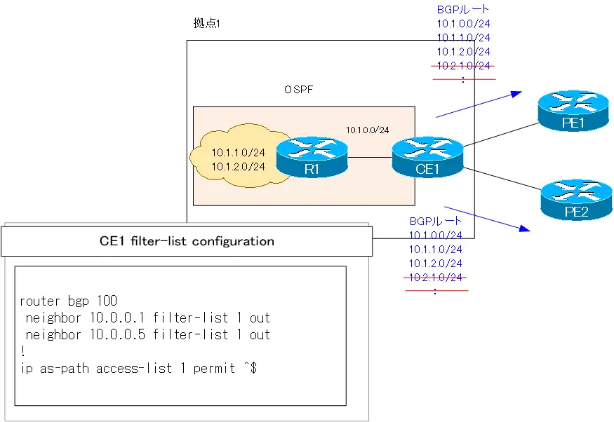
Step2:ルートフィルタの設定
CE1から拠点2のルートがアドバタイズされていてもPEルータ側でベストパスになることは通常ありませんが、不要なBGPルートをアドバタイズしてしまっていることになります。CE1からPE1/PE2へアドバタイズするルートは、拠点1のルートのみになるようにフィルターリストでフィルタします。
CE1 フィルターリスト
router bgp 100
 neighbor 10.0.0.1 filter-list 1 out
 neighbor 10.0.0.5 filter-list 1 out
!
ip as-path access-list 1 permit ^$
設定後、clear ip bgp * outでBGPルートの再送信が必要です。
Step3:ルートフィルタの確認
Step2の設定後、CE1からPE2へアドバタイズしているルートを確認します。
CE1 show ip bgp neighbor 10.0.0.5 advertised-routes
CE1#show ip bgp neighbors 10.0.0.5 advertised-routes
BGP table version is 24, local router ID is 10.1.0.1
Status codes: s suppressed, d damped, h history, * valid, > best, i - internal,
              r RIB-failure, S Stale
Origin codes: i - IGP, e - EGP, ? - incomplete

   Network          Next Hop            Metric LocPrf Weight Path
*> 10.1.0.0/24      0.0.0.0                  0         32768 i
*> 10.1.1.0/24      10.1.0.10               11         32768 i
*> 10.1.2.0/24      10.1.0.10               11         32768 i

Total number of prefixes 3
フィルターリストによって、CE1は拠点1のルート、つまり、AS_PATHが空っぽのルートのみをPE2へアドバタイズしていることがわかります。ディストリビュートリストやプレフィクスリストでも同じようなフィルタは可能ですが、フィルターリストの設定の方がシンプルです。
Step4:拠点2のルートのベストパスの確認
CE1で拠点2のルートのベストパスを確認します。
CE1 show ip bgp regexp ^1_
CE1#show ip bgp regexp ^1_
BGP table version is 24, local router ID is 10.1.0.1
Status codes: s suppressed, d damped, h history, * valid, > best, i - internal,
              r RIB-failure, S Stale
Origin codes: i - IGP, e - EGP, ? - incomplete

   Network          Next Hop            Metric LocPrf Weight Path
r  10.0.0.0/30      10.0.0.5                               0 1 i
r>                  10.0.0.1                 0             0 1 i
r  10.0.0.4/30      10.0.0.1                               0 1 i
r>                  10.0.0.5                 0             0 1 i
*  10.0.0.8/30      10.0.0.5                               0 1 i
*>                  10.0.0.1                               0 1 i
*  10.2.1.0/24      10.0.0.5                               0 1 i
*>                  10.0.0.1                               0 1 i
*  10.2.2.0/24      10.0.0.5                               0 1 i
*>                  10.0.0.1                               0 1 i
*  10.2.3.0/24      10.0.0.5                               0 1 i
*>                  10.0.0.1                               0 1 i
CE1#show ip route bgp
     10.0.0.0/8 is variably subnetted, 9 subnets, 2 masks
B       10.0.0.8/30 [20/0] via 10.0.0.1, 00:49:59
B       10.2.1.0/24 [20/0] via 10.0.0.1, 00:49:59
B       10.2.2.0/24 [20/0] via 10.0.0.1, 00:49:59
B       10.2.3.0/24 [20/0] via 10.0.0.1, 00:49:59
CE1から拠点2へのルートはすべてPE1がベストパスとなっていることがわかります。
Step5:拠点2あてのルーティングの負荷分散の設定
CE1から拠点2のルーティングがすべてPE1を経由するのではなく、PE1とPE2で分散されるようにします。
10.2.1.0/24あてのパケットがPE1を優先するためには、10.2.1.0/24のベストパスがPE1から受信したものになるようにします。つまり、PE1から受信する10.2.1.0/24のLOCAL_PREFERENCEを大きく設定します。同様に考えて、PE2から受信する10.2.2.0/24のLOCAL_PREFERENCEを大きく設定します。
そして、10.2.3.0/24あてのパケットをPE1とPE2で分散させるために、ルーティングテーブルに10.2.3.0/24のBGPルートが複数登録されるようにmaximum-pathsの設定を行います。
CE1 拠点2宛ての負荷分散
router bgp 100
 neighbor 10.0.0.1 route-map FromPE1 in
 neighbor 10.0.0.5 route-map FromPE2 in
 maximum-paths 2
!
access-list 1 permit 10.2.1.0
access-list 2 permit 10.2.2.0
!
route-map FromPE2 permit 10
 match ip address 2
 set local-preference 150
!
route-map FromPE2 permit 1000
!
route-map FromPE1 permit 10
 match ip address 1
 set local-preference 150
!
route-map FromPE1 permit 1000
Step6:拠点2あてのルーティングの負荷分散の確認
再度、CE1で拠点2のルートについてのベストパスを確認します。
CE1 show ip bgp regexp ^1_
CE1#show ip bgp regexp ^1
BGP table version is 32, local router ID is 10.1.0.1
Status codes: s suppressed, d damped, h history, * valid, > best, i - internal,
r RIB-failure, S Stale
Origin codes: i - IGP, e - EGP, ? - incomplete
Network Next Hop Metric LocPrf Weight Path
r 10.0.0.0/30 10.0.0.5 0 1 i
r> 10.0.0.1 0 0 1 i
r 10.0.0.4/30 10.0.0.1 0 1 i
r> 10.0.0.5 0 0 1 i
* 10.0.0.8/30 10.0.0.5 0 1 i
*> 10.0.0.1 0 1 i
* 10.2.1.0/24 10.0.0.5 0 1 i
*> 10.0.0.1 150 0 1 i
*> 10.2.2.0/24 10.0.0.5 150 0 1 i
* 10.0.0.1 0 1 i
* 10.2.3.0/24 10.0.0.5 0 1 i
*> 10.0.0.1 0 1 i
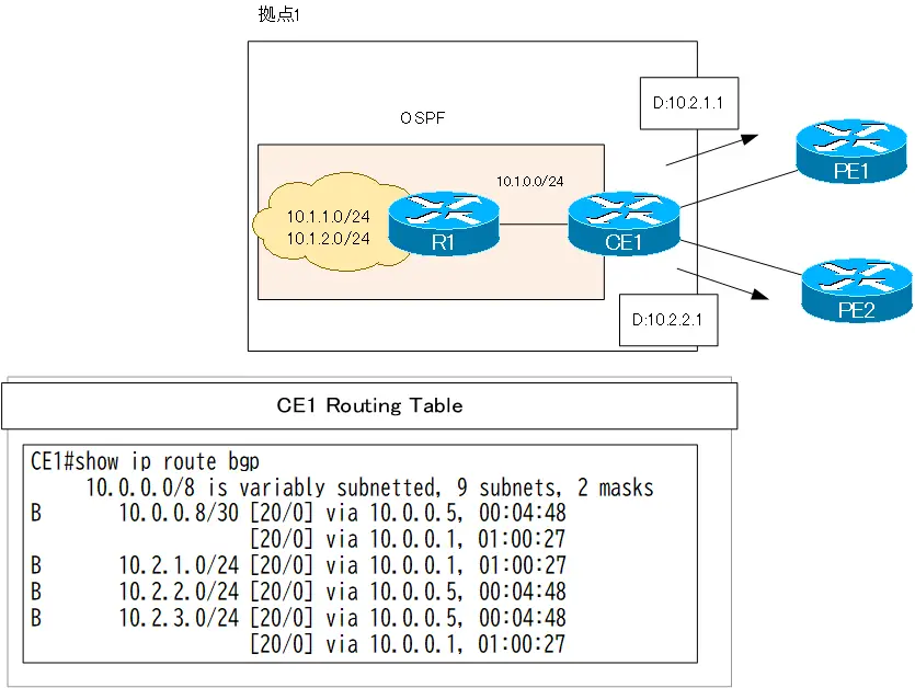
CE1#show ip route bgp
10.0.0.0/8 is variably subnetted, 9 subnets, 2 masks
B 10.0.0.8/30 [20/0] via 10.0.0.5, 00:04:48
[20/0] via 10.0.0.1, 01:00:27
B 10.2.1.0/24 [20/0] via 10.0.0.1, 01:00:27
B 10.2.2.0/24 [20/0] via 10.0.0.5, 00:04:48
B 10.2.3.0/24 [20/0] via 10.0.0.5, 00:04:48
[20/0] via 10.0.0.1, 01:00:27
10.2.1.0/24あてのパケットはPE1へ、10.2.2.0/24あてのパケットはPE2へルーティングすることがわかります。また、10.2.3.0/24あてのパケットはPE1とPE2で負荷分散されることもわかります。
Step7:拠点1のルートのベストパスの確認
拠点1内のルートへのベストパスを確認します。確認するべきルータはPE3です。PE3でMP-BGPテーブルとVRFのルーティングテーブルを確認します。
PE3 拠点1のルートの確認
PE3#show bgp vpnv4 unicast all regexp ^100_
BGP table version is 19, local router ID is 192.168.0.3
Status codes: s suppressed, d damped, h history, * valid, > best, i - internal,
              r RIB-failure, S Stale
Origin codes: i - IGP, e - EGP, ? - incomplete

   Network          Next Hop            Metric LocPrf Weight Path
Route Distinguisher: 1:100 (default for vrf VPN)
* i10.1.0.0/24      192.168.0.2              0    100      0 100 i
*>i                 192.168.0.1              0    100      0 100 i
* i10.1.1.0/24      192.168.0.2             11    100      0 100 i
*>i                 192.168.0.1             11    100      0 100 i
* i10.1.2.0/24      192.168.0.2             11    100      0 100 i
*>i                 192.168.0.1             11    100      0 100 i
PE3#show ip route  vrf VPN bgp
     10.0.0.0/8 is variably subnetted, 9 subnets, 2 masks
B       10.1.2.0/24 [200/11] via 192.168.0.1, 01:05:57
B       10.1.1.0/24 [200/11] via 192.168.0.1, 01:05:57
B       10.0.0.0/30 [200/0] via 192.168.0.1, 00:54:11
B       10.1.0.0/24 [200/0] via 192.168.0.1, 01:01:12
B       10.0.0.4/30 [200/0] via 192.168.0.2, 00:53:56
PE3から拠点1の10.1.1.0/24、10.1.2.0/24あてのパケットはすべてPE1を経由することがわかります。
Step8:拠点1あてのルーティングの負荷分散の設定
拠点1あてのルーティングがすべてPE1を経由するのではなく、PE1とPE2で分散させます。
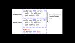
10.1.1.0/24あてのパケットがPE1を優先して経由するために、CE1からPE1へアドバタイズする10.1.1.0/24のMEDを小さくします。同様に、10.1.2.0/24あてのパケットがPE2を優先して経由するために、CE1からPE2へアドバタイズする10.1.2.0/24のMEDを小さくします。
CE1 拠点1宛ての負荷分散
router bgp 100
 neighbor 10.0.0.1 route-map ToPE1 out
 neighbor 10.0.0.5 route-map ToPE2 out
!
access-list 3 permit 10.1.1.0
access-list 4 permit 10.1.2.0
!
route-map ToPE2 permit 10
 match ip address 4
 set metric 1
!
route-map ToPE2 permit 20
 set metric 100
!
route-map ToPE1 permit 10
 match ip address 3
 set metric 1
!
route-map ToPE1 permit 20
 set metric 100
Step9:拠点1あてのルーティングの負荷分散の確認
再度、PE3で拠点1のルートのベストパスを確認します。
PE3 拠点1のルートの確認
PE3#show bgp vpnv4 unicast all regexp ^100_
BGP table version is 29, local router ID is 192.168.0.3
Status codes: s suppressed, d damped, h history, * valid, > best, i - internal,
r RIB-failure, S Stale
Origin codes: i - IGP, e - EGP, ? - incomplete
Network Next Hop Metric LocPrf Weight Path
Route Distinguisher: 1:100 (default for vrf VPN)
* i10.1.0.0/24 192.168.0.2 100 100 0 100 i
*>i 192.168.0.1 100 100 0 100 i
*>i10.1.1.0/24 192.168.0.1 1 100 0 100 i
*>i10.1.2.0/24 192.168.0.2 1 100 0 100 i
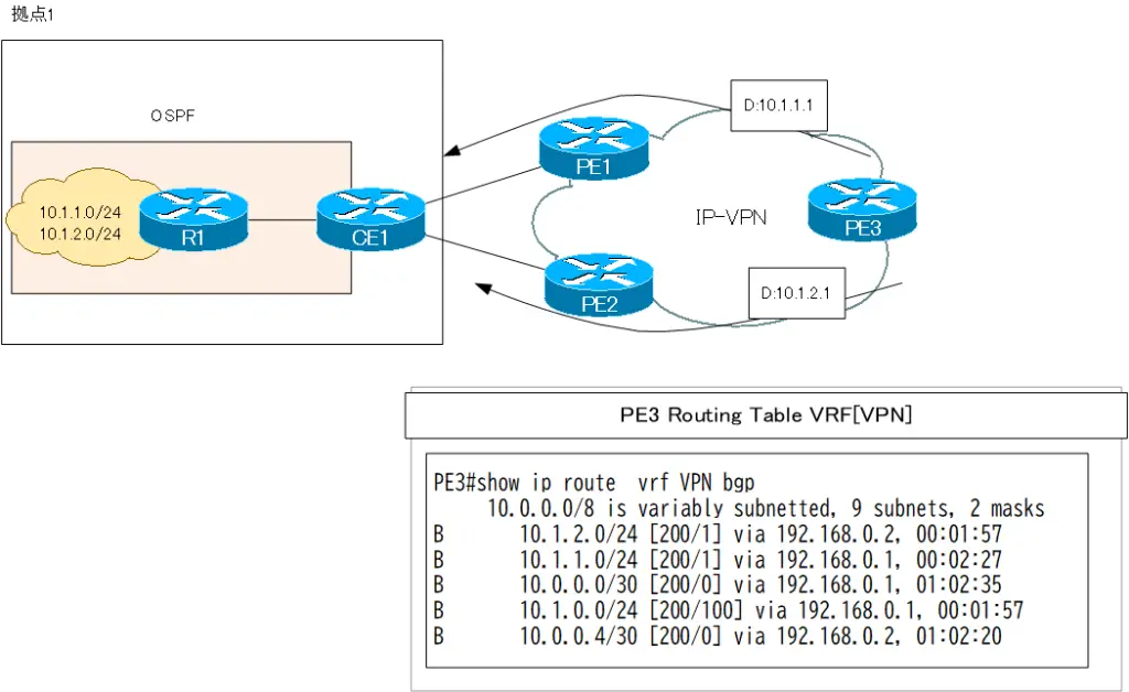
PE3#show ip route vrf VPN bgp
10.0.0.0/8 is variably subnetted, 9 subnets, 2 masks
B 10.1.2.0/24 [200/1] via 192.168.0.2, 00:01:57
B 10.1.1.0/24 [200/1] via 192.168.0.1, 00:02:27
B 10.0.0.0/30 [200/0] via 192.168.0.1, 01:02:35
B 10.1.0.0/24 [200/100] via 192.168.0.1, 00:01:57
B 10.0.0.4/30 [200/0] via 192.168.0.2, 01:02:20
PE3から10.1.1.0/24あてにパケットをルーティングするときにはPE1を経由し、10.1.2.0/24あてにパケットをルーティングするときにはPE2を経由することがわかります。
関連記事
関連記事
このページの設定に関連する以下の記事もあわせてご覧ください。


BGPの仕組み
- BGPの概要 ~AS間でルート情報を交換~
- BGPの動作
- BGPの基本設定と確認コマンド
- BGPピアグループ(Peer Group) ~ネイバーの設定をまとめよう~
- BGPネイバーの状態
- BGPコンフェデレーションの設定
- BGPコンフェデレーションの設定例
- BGPネイバー認証
- BGP Well Known Mandatory アトリビュート -ORIGIN/AS_PATH/NEXT_HOP-
- 図解!BGPベストパス選択アルゴリズム
- BGP 基本的な設定についての演習[Cisco]
- BGPの基本的な設定についての演習 ~トラブルシュート~
- BGP KEEPALIVEタイマ/ホールドタイムの設定
- BGPルート 最小送信間隔の設定
- BGPルートダンプニング
- マルチホーム – インターネット接続の冗長化 –
- マルチホームAS BGPルートフィルタのポイント
- マルチホームAS ベストパス選択のポイント
- マルチホームAS IGPとBGPの連携のポイント
- マルチホームAS BGPの設定例
- IP-VPNでのBGPの利用 設定例
- BGPルートフィルタの種類
- BGPルートフィルタ -ディストリビュートリスト-
- BGPルートフィルタ -ディストリビュートリスト設定例-
- BGPルートフィルタ -プレフィクスリスト-
- BGPルートフィルタ -プレフィクスリスト設定例-
- BGPルートフィルタ -フィルタリスト(AS_PATH ACL)-
- BGPルートフィルタ -フィルタリスト(AS_PATH ACL)設定例-
- BGPルートフィルタ -ルートマップ(route-map)-
- BGPルートフィルタ -ルートマップ(route-map)設定例-
- BGP neighbor allowas-inコマンド
- BGP neighbor as-overrideコマンド
- BGPルート RIB Failure
- BGPルート アドミニストレイティブディスタンスの制御
- BGPルートの負荷分散
- BGPルート 条件付き生成
- BGPルート 条件付きアドバタイズ
- BGP ルート集約 自動集約
- BGPルート集約 networkコマンドによる集約
- BGPルート集約 networkコマンドによる集約 設定例
- BGP ルート集約 aggregate-addressコマンドによる集約
- aggregate-addressコマンドのオプション summary-only
- aggregate-addressコマンドのオプション attribute-map
- aggregate-addressコマンドのオプション as-set
- aggregate-addressコマンドのオプション advertise-map
- aggregate-addressコマンド as-set/attribute-map/advertise-map 設定例
- BGP選択型集約の概要
- BGP選択型集約 suppress-map
- BGP選択型集約 unsuppress-map
- BGP 選択型集約 suppress-map/unsuppress-map 設定例
- BGP local-as ~ネイバーに他のASのように見せる~
- BGP neighbor remove-private-ASコマンド
- bgp fast external-fallover
- BGP プレフィクス数の制限
- BGP COMMUNITYアトリビュートの使い方
- BGP Well-known COMMUNITYのルートフィルタ設定例
- BGP プライベートCOMMUNITYによるルート制御の設定例
- [演習]BGP応用 Part1:BGP基本設定
- [演習]BGP応用 Part2:ルート集約
- [演習]BGP応用 Part3:ポリシーベースルーティング
- [演習]BGP応用 Part4:トラブルシューティング
- BGP 設定ミスの切り分けと修正 Part1
- BGP 設定ミスの切り分けと修正 Part2
- BGP 設定ミスの切り分けと修正 Part3
- BGP 設定ミスの切り分けと修正 Part4
- BGP 設定ミスの切り分けと修正 Part5
- BGP 設定ミスの切り分けと修正 Part6
- BGP 設定ミスの切り分けと修正 Part7
- IPv6 BGPの設定例 Part1
- IPv6 BGPの設定例 Part2
- 2021年10月4日 Facebookに何が起こったか?
- IPv4 BGPネイバーでのIPv6プレフィックスの交換
