目次
概要
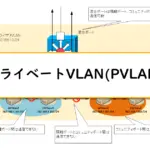
プライベートVLAN(PVLAN)の設定例です。同一のIPネットワーク内でプライベートVLANを利用して、通信できる範囲を制御します。
関連記事
プライベートVLAN(PVLAN)の設定、確認コマンドについて、以下の記事もあわせてご覧ください。
ネットワーク構成
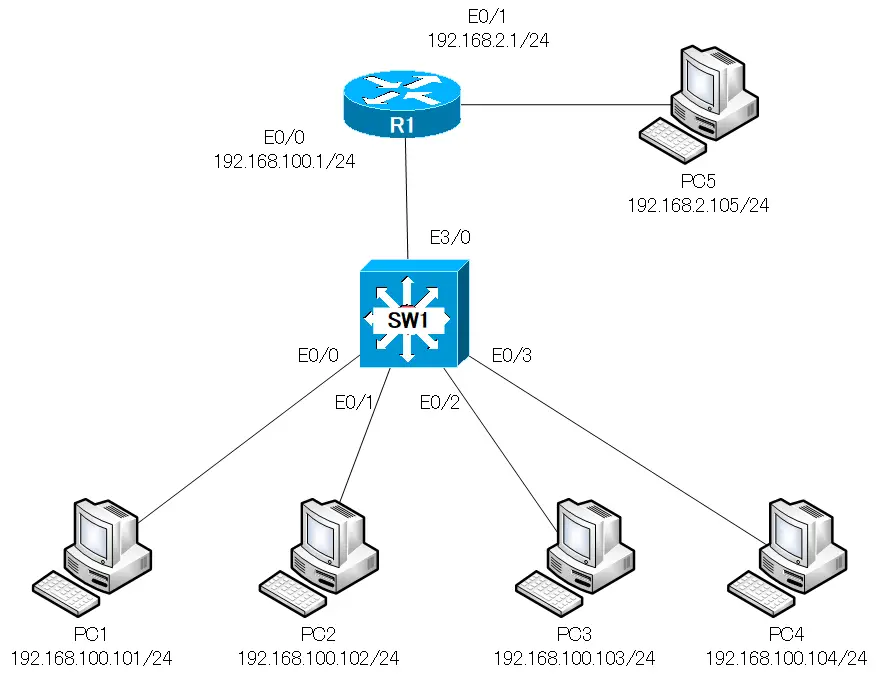
設定条件
- プライベートVLANによって、192.168.100.0/24内で以下のように通信できる範囲を制御します。
- PC1/PC2はデフォルトゲートウェイR1とのみ通信する
- PC3/PC4は、お互いとデフォルトゲートウェイR1と通信する
初期設定
R1
R1はIPアドレスを設定して、直接接続のネットワーク間で通信できるようにしています。
R1 Initial Configuration
hostname R1-IOU
!
interface Ethernet0/0
 ip address 192.168.100.1 255.255.255.0
!
interface Ethernet0/1
 ip address 192.168.2.1 255.255.255.0
SW1
SW1はPC1-PC4およびR1が接続されているインタフェースをVLAN100のアクセスポートとして設定しています。
SW1 Initial Configuration
hostname SW1-IOU
!
interface Ethernet0/0
 switchport access vlan 100
!
interface Ethernet0/1
 switchport access vlan 100
!
interface Ethernet0/2
 switchport access vlan 100
!
interface Ethernet0/3
 switchport access vlan 100
!
interface Ethernet3/0
 switchport access vlan 100
PC1-PC5
IPアドレスおよびデフォルトゲートウェイを設定しています。
設定と確認
Step1:VTPトランスペアレントの設定
プライベートVLANは、VTPv1/v2ではトランスペアレントモードにしなければいけません。トランスペアレントモードでないと、以下のようなエラーメッセージが表示されます。
PVLAN設定時のエラー
SW1-IOU(config)#vlan 100
SW1-IOU(config-vlan)#private-vlan primary
%Private VLANs can only be configured when VTP is in transparent/off modes in VTP version 1 or 2 and in server/transparent/off modes in VTP version 3 when pruning is turned off
SW1でVTPモードをトランスペアレントにします。また、既存のVLAN100のアクセスポートの設定を削除します。
SW1 VTPトランスペアレント
vtp mode transparent
!
interface range Ethernet0/0-3,Ethernet3/0
 no switchport access vlan
Step2:プライベートVLANの作成
192.168.100.0/24内で通信できる範囲を制御するためにプライベートVLANを作成します。現在設定済みのVLAN100をプライマリVLANとします。そして、隔離VLANとコミュニティVLANを作成します。
| VLAN ID | プライベートVLAN |
|---|---|
| 100 | プライマリVLAN |
| 10 | 隔離VLAN |
| 20 | コミュニティVLAN |
SW1 プライベートVLANの作成
vlan 100
  private-vlan primary
  private-vlan association 10,20
!
vlan 10
  private-vlan isolated
!
vlan 20
  private-vlan community
Step3:プライベートVLANのポートの設定
プライベートVLANのポートの設定を行います。
混合(Promiscuous)ポート
192.168.100.0/24のデフォルトゲートウェイとなるR1が接続されているEthernet3/0を混合ポートにします。
隔離(Isolated)ポート
PC1とPC2はデフォルトゲートウェイのR1とのみ通信するので、PC1/PC2が接続されているEthenert0/0、Ethernet0/1を隔離ポートにします。
コミュニティ(Community)ポート
PC3とPC4は、お互いとデフォルトゲートウェイのR1と通信するので、PC3/PC4が接続されているEthernet0/2、Ethernet0/3をコミュニティポートにします。
設定するプライベートVLANのポートを以下の表にまとめています。
| ポートの種類 | インタフェース名 | 接続先 |
|---|---|---|
| 混合ポート | Ethernet3/0 | R1 |
| 隔離ポート(VLAN10) | Ethernet0/0、Ethernet0/1 | PC1/PC2 |
| コミュニティポート(VLAN20) | Ethernet0/2、Ethernet0/3 | PC3/PC4 |
SW1 プライベートVLANのポートの設定
interface Ethernet0/0
 switchport private-vlan host-association 100 10
 switchport mode private-vlan host
!
interface Ethernet0/1
 switchport private-vlan host-association 100 10
 switchport mode private-vlan host
!
interface Ethernet0/2
 switchport private-vlan host-association 100 20
 switchport mode private-vlan host
!
interface Ethernet0/3
 switchport private-vlan host-association 100 20
 switchport mode private-vlan host
!
interface Ethernet3/0
 switchport private-vlan mapping 100 10,20
 switchport mode private-vlan promiscuous
Step4:プライベートVLANの確認
ここまでのプライベートVLANの設定が正しく行われていることを確認します。SW1で次のshowコマンドを利用します。
| コマンド | 概要 |
|---|---|
| #show vlan private-vlan | プライマリ/セカンダリVLANとポートを表示します。 |
| #show interface switchport | インタフェースのプライベートVLANの割り当ての詳細を表示します。 |
SW1 show vlan private-vlan
SW1-IOU#show vlan private-vlan

Primary Secondary Type              Ports
------- --------- ----------------- ------------------------------------------
100     10        isolated          Et0/0, Et0/1, Et3/0
100     20        community         Et0/2, Et0/3, Et3/0
SW1 show interface switchport
SW1-IOU#show interfaces Ethernet0/0 switchport
Name: Et0/0
Switchport: Enabled
Administrative Mode: private-vlan host
Operational Mode: private-vlan host
Administrative Trunking Encapsulation: negotiate
Operational Trunking Encapsulation: native
Negotiation of Trunking: Off
Access Mode VLAN: 1 (default)
Trunking Native Mode VLAN: 1 (default)
Administrative Native VLAN tagging: enabled
Voice VLAN: none
Administrative private-vlan host-association: 100 (VLAN0100) 10 (VLAN0010)
Administrative private-vlan mapping: none
Administrative private-vlan trunk native VLAN: none
Administrative private-vlan trunk Native VLAN tagging: enabled
Administrative private-vlan trunk encapsulation: dot1q
Administrative private-vlan trunk normal VLANs: none
Administrative private-vlan trunk associations: none
Administrative private-vlan trunk mappings: none
Operational private-vlan:
  100 (VLAN0100) 10 (VLAN0010)
-- omitted --
SW1-IOU#show interfaces Ethernet0/2 switchport
Name: Et0/2
Switchport: Enabled
Administrative Mode: private-vlan host
Operational Mode: private-vlan host
Administrative Trunking Encapsulation: negotiate
Operational Trunking Encapsulation: native
Negotiation of Trunking: Off
Access Mode VLAN: 1 (default)
Trunking Native Mode VLAN: 1 (default)
Administrative Native VLAN tagging: enabled
Voice VLAN: none
Administrative private-vlan host-association: 100 (VLAN0100) 20 (VLAN0020)
Administrative private-vlan mapping: none
Administrative private-vlan trunk native VLAN: none
Administrative private-vlan trunk Native VLAN tagging: enabled
Administrative private-vlan trunk encapsulation: dot1q
Administrative private-vlan trunk normal VLANs: none
Administrative private-vlan trunk associations: none
Administrative private-vlan trunk mappings: none
Operational private-vlan:
  100 (VLAN0100) 20 (VLAN0020)
-- omitted --
SW1-IOU#show interfaces Ethernet3/0 switchport
Name: Et3/0
Switchport: Enabled
Administrative Mode: private-vlan promiscuous
Operational Mode: private-vlan promiscuous
Administrative Trunking Encapsulation: negotiate
Operational Trunking Encapsulation: native
Negotiation of Trunking: Off
Access Mode VLAN: 1 (default)
Trunking Native Mode VLAN: 1 (default)
Administrative Native VLAN tagging: enabled
Voice VLAN: none
Administrative private-vlan host-association: none
Administrative private-vlan mapping: 100 (VLAN0100) 10 (VLAN0010) 20 (VLAN0020)
Administrative private-vlan trunk native VLAN: none
Administrative private-vlan trunk Native VLAN tagging: enabled
Administrative private-vlan trunk encapsulation: dot1q
Administrative private-vlan trunk normal VLANs: none
Administrative private-vlan trunk associations: none
Administrative private-vlan trunk mappings: none
Operational private-vlan:
  100 (VLAN0100) 10 (VLAN0010) 20 (VLAN0020)
-- omitted --
Step5:通信確認
条件通りにPC1-PC4の通信の制御ができていることを確認します。
PC1
PC1は、PC2からPC4との通信はできません。デフォルトゲートウェイとの通信はできるのでPC5との通信は可能です。
PC1 プライベートVLANの通信確認
PC1> ping 192.168.100.102

host (192.168.100.102) not reachable

PC1> ping 192.168.100.103

host (192.168.100.103) not reachable

PC1> ping 192.168.100.104

host (192.168.100.104) not reachable

PC1> ping 192.168.100.1

84 bytes from 192.168.100.1 icmp_seq=1 ttl=255 time=0.267 ms
84 bytes from 192.168.100.1 icmp_seq=2 ttl=255 time=0.373 ms
84 bytes from 192.168.100.1 icmp_seq=3 ttl=255 time=0.449 ms
84 bytes from 192.168.100.1 icmp_seq=4 ttl=255 time=0.444 ms
84 bytes from 192.168.100.1 icmp_seq=5 ttl=255 time=0.577 ms

PC1> ping 192.168.2.105

84 bytes from 192.168.2.105 icmp_seq=1 ttl=63 time=5.027 ms
84 bytes from 192.168.2.105 icmp_seq=2 ttl=63 time=1.454 ms
84 bytes from 192.168.2.105 icmp_seq=3 ttl=63 time=0.884 ms
84 bytes from 192.168.2.105 icmp_seq=4 ttl=63 time=1.328 ms
84 bytes from 192.168.2.105 icmp_seq=5 ttl=63 time=1.003 ms
PC2もPC1と同様です。
PC3
PC3はPC4およびPC5との通信ができます。
PC1 プライベートVLANの通信確認
PC3> ping 192.168.100.101

host (192.168.100.101) not reachable

PC3> ping 192.168.100.102

host (192.168.100.102) not reachable

PC3> ping 192.168.100.104

84 bytes from 192.168.100.104 icmp_seq=1 ttl=64 time=0.387 ms
84 bytes from 192.168.100.104 icmp_seq=2 ttl=64 time=0.599 ms
84 bytes from 192.168.100.104 icmp_seq=3 ttl=64 time=0.353 ms
84 bytes from 192.168.100.104 icmp_seq=4 ttl=64 time=0.684 ms
84 bytes from 192.168.100.104 icmp_seq=5 ttl=64 time=0.432 ms

PC3> ping 192.168.100.1

84 bytes from 192.168.100.1 icmp_seq=1 ttl=255 time=0.936 ms
84 bytes from 192.168.100.1 icmp_seq=2 ttl=255 time=0.586 ms
84 bytes from 192.168.100.1 icmp_seq=3 ttl=255 time=0.943 ms
84 bytes from 192.168.100.1 icmp_seq=4 ttl=255 time=0.711 ms
84 bytes from 192.168.100.1 icmp_seq=5 ttl=255 time=0.757 ms

PC3> ping 192.168.2.105

84 bytes from 192.168.2.105 icmp_seq=1 ttl=63 time=0.613 ms
84 bytes from 192.168.2.105 icmp_seq=2 ttl=63 time=1.271 ms
84 bytes from 192.168.2.105 icmp_seq=3 ttl=63 time=0.926 ms
84 bytes from 192.168.2.105 icmp_seq=4 ttl=63 time=0.762 ms
84 bytes from 192.168.2.105 icmp_seq=5 ttl=63 time=1.277 ms
PC4もPC3と同様です。
設定のまとめ
以下の図に、SW1でのプライベートVLANの設定と通信できる範囲をまとめています。

SW1 PVLAN Configuration
vlan 100
  private-vlan primary
  private-vlan association 10,20
!
vlan 10
  private-vlan isolated
!
vlan 20
  private-vlan community
!
interface Ethernet0/0
 switchport private-vlan host-association 100 10
 switchport mode private-vlan host
!
interface Ethernet0/1
 switchport private-vlan host-association 100 10
 switchport mode private-vlan host
!
interface Ethernet0/2
 switchport private-vlan host-association 100 20
 switchport mode private-vlan host
!
interface Ethernet0/3
 switchport private-vlan host-association 100 20
 switchport mode private-vlan host
!
interface Ethernet3/0
 switchport private-vlan mapping 100 10,20
 switchport mode private-vlan promiscuous

VLAN(Virtual LAN)の仕組み
- ネットワークを分割する必要性
- ネットワークを分割することの詳細
- VLANの概要
- VLANの仕組み
- アクセスポート ~1つのVLANのみに割り当てるポート~
- トランクポート(タグVLAN) ~複数のVLANに割り当てるポート~
- トランクプロトコルのまとめ ~IEEE802.1QとISL~
- ネイティブVLAN
- ネイティブVLAN不一致の具体例
- ホストでのトランクポートの利用 ~PC/サーバのポートを分割~
- VLANの仕組みをより深く理解する
- VLANの仕組みをより深く理解するための演習
- Cisco DTP ~対向ポートに合わせてトランクポート/アクセスポートに~
- 複数スイッチをまたがるVLANの注意点
- Cisco VLANの設定と確認コマンドを詳しく解説!これでCiscoのVLANの設定はマスター
- Cisco VLANの詳細な設定例
- VLANを削除するときの注意点
- Voice VLAN ~IP PhoneをつなげるためのVLAN~
- VTP ~VLANの設定情報を同期~
- VTPプルーニング ~トランクリンクへの不要なフラッディングを止める~
- VTPの設定と確認
- VLAN間ルーティングの概要
- ルータによるVLAN間ルーティング
- レイヤ3スイッチによるVLAN間ルーティング
- Cisco ルータによるVLAN間ルーティングの設定と確認
- Cisco レイヤ3スイッチによるVLAN間ルーティングの設定(SVI/ルーテッドポート)
- Cisco レイヤ3スイッチ 基本的な設定例
- 演習:レイヤ3スイッチの基本[Cisco]
- 「VLANにIPアドレスを設定する」は間違い
- レイヤ3スイッチのポートの考え方のまとめ ~アクセスポート/トランクポート/SVI/ルーテッドポート~
- プライベートVLAN
- プライベートVLANの設定例
- LANの構成パターン ~2ティア/3ティア~