目次
概要
BSRでRPアドレスをダイナミックに学習することについて設定ミスの切り分けと修正を行います。
ネットワーク構成
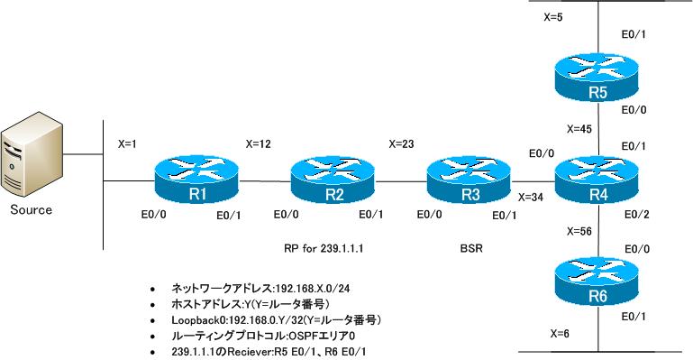
下記のネットワーク構成で、PIM-SMによるマルチキャストルーティングを行っています。
設定概要
各ルータで行われているPIM-SMに関する設定は次の通りです。これらの設定には一部設定ミスがあります。
R1
ip multicast-routing
!
interface Loopback0
 ip address 192.168.0.1 255.255.255.255
 ip pim sparse-mode
!
interface Ethernet0/0
 ip address 192.168.1.1 255.255.255.0
!
interface Ethernet0/1
 ip address 192.168.12.1 255.255.255.0
 ip pim sparse-mode
!
router ospf 1
 log-adjacency-changes
 network 192.168.0.0 0.0.255.255 area 0
R2
ip multicast-routing
!
interface Loopback0
 ip address 192.168.0.2 255.255.255.255
 ip pim sparse-mode
!
interface Ethernet0/0
 ip address 192.168.12.2 255.255.255.0
 ip pim sparse-mode
!
interface Ethernet0/1
 ip address 192.168.23.2 255.255.255.0
 ip pim sparse-mode
!
router ospf 1
 log-adjacency-changes
 network 192.168.0.0 0.0.255.255 area 0
!
ip pim rp-candidate Loopback0 group-list 1 interval 5
!
access-list 1 permit 239.1.0.1
R3
ip multicast-routing
!
interface Loopback0
 ip address 192.168.0.3 255.255.255.255
!
interface Ethernet0/0
 ip address 192.168.23.3 255.255.255.0
 ip pim sparse-mode
!
interface Ethernet0/1
 ip address 192.168.34.3 255.255.255.0
 ip pim sparse-mode
!
router ospf 1
 log-adjacency-changes
 network 192.168.0.0 0.0.255.255 area 0
!
ip pim bsr-candidate Loopback0 0
R4
ip multicast-routing
!
interface Loopback0
 ip address 192.168.0.4 255.255.255.255
 ip pim sparse-mode
!
interface Ethernet0/0
 ip address 192.168.34.4 255.255.255.0
 ip pim bsr-border
 ip pim sparse-mode
!
interface Ethernet0/1
 ip address 192.168.45.4 255.255.255.0
 ip pim sparse-mode
!
interface Ethernet0/2
 ip address 192.168.46.4 255.255.255.0
 ip pim sparse-mode
!
router ospf 1
 log-adjacency-changes
 network 192.168.0.0 0.0.255.255 area 0
R5
ip multicast-routing
!
interface Loopback0
 ip address 192.168.0.5 255.255.255.255
 ip pim sparse-mode
!
interface Ethernet0/0
 ip address 192.168.45.5 255.255.255.0
 ip pim sparse-mode
!
interface Ethernet0/1
 ip address 192.168.5.5 255.255.255.0
 ip pim sparse-mode
 ip igmp join-group 239.1.1.1
!
router ospf 1
 log-adjacency-changes
 network 192.168.0.0 0.0.255.255 area 0
R6
ip multicast-routing
!
interface Loopback0
 ip address 192.168.0.6 255.255.255.255
 ip pim sparse-mode
!
interface Ethernet0/0
 ip address 192.168.46.6 255.255.255.0
 ip pim sparse-mode
!
interface Ethernet0/1
 ip address 192.168.6.6 255.255.255.0
 ip pim sparse-mode
 ip igmp join-group 239.1.1.1
!
router ospf 1
 log-adjacency-changes
 network 192.168.0.0 0.0.255.255 area 0
SOURCE
interface Ethernet0/0
 ip address 192.168.1.100 255.255.255.0
!
ip route 0.0.0.0 0.0.0.0 192.168.1.1
トラブルの症状
SOURCEから送信したマルチキャストグループ239.1.1.1のパケットが正しくルーティングされません。どうやら、R1~R4の間でいくつかの設定ミスが重なっているようです。R5/R6/SOURCEには設定ミスはないことが確実に分かっています。そこで、R1~R4でトラブルを切り分けるために各ルータでshowコマンドを実行しました。
R1/R3
show ip pim interface
show ip pim neighbor
show ip pim bsr-router
show ip pim rp mapping
show ip mroute
R2
show ip pim interface
show ip pim neighbor
show ip pim bsr-router
show ip pim rp mapping
show access-list
show ip mroute
R4
show ip pim interface detail
show ip pim neighbor
show ip pim bsr-router
show ip pim rp mapping
show ip mroute
R1
R1#show ip pim interface

Address          Interface                Ver/   Nbr    Query  DR     DR
                                          Mode   Count  Intvl  Prior
192.168.0.1      Loopback0                v2/S   0      30     1      192.168.0.1
192.168.12.1     Ethernet0/1              v2/S   1      30     1      192.168.12.2
R1#show ip pim neighbor
PIM Neighbor Table
Mode: B - Bidir Capable, DR - Designated Router, N - Default DR Priority,
      S - State Refresh Capable
Neighbor          Interface                Uptime/Expires    Ver   DR
Address                                                            Prio/Mode
192.168.12.2      Ethernet0/1              00:42:33/00:01:33 v2    1 / DR S
R1#show ip pim bsr-router
PIMv2 Bootstrap information
R1#show ip pim rp mapping
PIM Group-to-RP Mappings

R1#show ip mroute
IP Multicast Routing Table
Flags: D - Dense, S - Sparse, B - Bidir Group, s - SSM Group, C - Connected,
       L - Local, P - Pruned, R - RP-bit set, F - Register flag,
       T - SPT-bit set, J - Join SPT, M - MSDP created entry,
       X - Proxy Join Timer Running, A - Candidate for MSDP Advertisement,
       U - URD, I - Received Source Specific Host Report,
       Z - Multicast Tunnel, z - MDT-data group sender,
       Y - Joined MDT-data group, y - Sending to MDT-data group
Outgoing interface flags: H - Hardware switched, A - Assert winner
 Timers: Uptime/Expires
 Interface state: Interface, Next-Hop or VCD, State/Mode

(*, 224.0.1.40), 00:35:43/00:02:15, RP 0.0.0.0, flags: DCL
  Incoming interface: Null, RPF nbr 0.0.0.0
  Outgoing interface list:
    Loopback0, Forward/Sparse, 00:35:43/00:02:15
R2
R2#show ip pim interface

Address          Interface                Ver/   Nbr    Query  DR     DR
                                          Mode   Count  Intvl  Prior
192.168.0.2      Loopback0                v2/S   0      30     1      192.168.0.2
192.168.12.2     Ethernet0/0              v2/S   1      30     1      192.168.12.2
192.168.23.2     Ethernet0/1              v2/S   1      30     1      192.168.23.3
R2#show ip pim neighbor
PIM Neighbor Table
Mode: B - Bidir Capable, DR - Designated Router, N - Default DR Priority,
      S - State Refresh Capable
Neighbor          Interface                Uptime/Expires    Ver   DR
Address                                                            Prio/Mode
192.168.12.1      Ethernet0/0              00:42:37/00:01:27 v2    1 / S
192.168.23.3      Ethernet0/1              00:43:01/00:01:37 v2    1 / DR S
R2#show ip pim bsr-router
PIMv2 Bootstrap information
  Candidate RP: 192.168.0.2(Loopback0)
    Holdtime 12 seconds
    Advertisement interval 5 seconds
    Next advertisement in 00:00:04
    Group acl: 1
R2#show ip pim rp mapping
PIM Group-to-RP Mappings
This system is a candidate RP (v2)

R2#show access-list
Standard IP access list 1
    10 permit 239.1.0.1
R2#show ip mroute
IP Multicast Routing Table
Flags: D - Dense, S - Sparse, B - Bidir Group, s - SSM Group, C - Connected,
       L - Local, P - Pruned, R - RP-bit set, F - Register flag,
       T - SPT-bit set, J - Join SPT, M - MSDP created entry,
       X - Proxy Join Timer Running, A - Candidate for MSDP Advertisement,
       U - URD, I - Received Source Specific Host Report,
       Z - Multicast Tunnel, z - MDT-data group sender,
       Y - Joined MDT-data group, y - Sending to MDT-data group
Outgoing interface flags: H - Hardware switched, A - Assert winner
 Timers: Uptime/Expires
 Interface state: Interface, Next-Hop or VCD, State/Mode

(*, 224.0.1.40), 00:35:43/00:02:54, RP 0.0.0.0, flags: DCL
  Incoming interface: Null, RPF nbr 0.0.0.0
  Outgoing interface list:
    Loopback0, Forward/Sparse, 00:35:43/00:02:51
R3
R3#show ip pim interface

Address          Interface                Ver/   Nbr    Query  DR     DR
                                          Mode   Count  Intvl  Prior
192.168.23.3     Ethernet0/0              v2/S   1      30     1      192.168.23.3
192.168.34.3     Ethernet0/1              v2/S   1      30     1      192.168.34.4
R3#show ip pim neighbor
PIM Neighbor Table
Mode: B - Bidir Capable, DR - Designated Router, N - Default DR Priority,
      S - State Refresh Capable
Neighbor          Interface                Uptime/Expires    Ver   DR
Address                                                            Prio/Mode
192.168.23.2      Ethernet0/0              00:45:14/00:01:23 v2    1 / S
192.168.34.4      Ethernet0/1              00:33:25/00:01:25 v2    1 / DR S
R3#show ip pim bsr-router
PIMv2 Bootstrap information
This system is a candidate BSR
  Candidate BSR interface Loopback0
    PIMv2 is not configured - BSR messages not originated
R3#show ip pim rp mapping
PIM Group-to-RP Mappings

R3#show ip mroute
IP Multicast Routing Table
Flags: D - Dense, S - Sparse, B - Bidir Group, s - SSM Group, C - Connected,
       L - Local, P - Pruned, R - RP-bit set, F - Register flag,
       T - SPT-bit set, J - Join SPT, M - MSDP created entry,
       X - Proxy Join Timer Running, A - Candidate for MSDP Advertisement,
       U - URD, I - Received Source Specific Host Report,
       Z - Multicast Tunnel, z - MDT-data group sender,
       Y - Joined MDT-data group, y - Sending to MDT-data group
Outgoing interface flags: H - Hardware switched, A - Assert winner
 Timers: Uptime/Expires
 Interface state: Interface, Next-Hop or VCD, State/Mode

(*, 224.0.1.40), 00:37:28/00:02:15, RP 0.0.0.0, flags: DCL
  Incoming interface: Null, RPF nbr 0.0.0.0
  Outgoing interface list:
    Ethernet0/0, Forward/Sparse, 00:22:01/00:02:15
R4
R4#show ip pim interface detail
Loopback0 is up, line protocol is up
  Internet address is 192.168.0.4/32
  Multicast switching: fast
  Multicast packets in/out: 0/0
  Multicast TTL threshold: 0
  PIM: enabled
    PIM version: 2, mode: sparse
    PIM DR: 192.168.0.4 (this system)
    PIM neighbor count: 0
    PIM Hello/Query interval: 30 seconds
    PIM Hello packets in/out: 95/96
    PIM State-Refresh processing: enabled
    PIM State-Refresh origination: disabled
    PIM NBMA mode: disabled
    PIM ATM multipoint signalling: disabled
    PIM domain border: disabled
  Multicast Tagswitching: disabled
Ethernet0/0 is up, line protocol is up
  Internet address is 192.168.34.4/24
  Multicast switching: fast
  Multicast packets in/out: 75/0
  Multicast TTL threshold: 0
  PIM: enabled
    PIM version: 2, mode: sparse
    PIM DR: 192.168.34.4 (this system)
    PIM neighbor count: 1
    PIM Hello/Query interval: 30 seconds
    PIM Hello packets in/out: 96/99
    PIM State-Refresh processing: enabled
    PIM State-Refresh origination: disabled
    PIM NBMA mode: disabled
    PIM ATM multipoint signalling: disabled
    PIM domain border: enabled
  Multicast Tagswitching: disabled
Ethernet0/1 is up, line protocol is up
  Internet address is 192.168.45.4/24
  Multicast switching: fast
  Multicast packets in/out: 0/2
  Multicast TTL threshold: 0
  PIM: enabled
    PIM version: 2, mode: sparse
    PIM DR: 192.168.45.5
    PIM neighbor count: 1
    PIM Hello/Query interval: 30 seconds
    PIM Hello packets in/out: 96/97
    PIM State-Refresh processing: enabled
    PIM State-Refresh origination: disabled
    PIM NBMA mode: disabled
    PIM ATM multipoint signalling: disabled
    PIM domain border: disabled
  Multicast Tagswitching: disabled
Ethernet0/2 is up, line protocol is up
  Internet address is 192.168.46.4/24
  Multicast switching: fast
  Multicast packets in/out: 0/2
  Multicast TTL threshold: 0
  PIM: enabled
    PIM version: 2, mode: sparse
    PIM DR: 192.168.46.6
    PIM neighbor count: 1
    PIM Hello/Query interval: 30 seconds
    PIM Hello packets in/out: 96/97
    PIM State-Refresh processing: enabled
    PIM State-Refresh origination: disabled
    PIM NBMA mode: disabled
    PIM ATM multipoint signalling: disabled
    PIM domain border: disabled
  Multicast Tagswitching: disabled
R4#show ip pim neighbor
PIM Neighbor Table
Mode: B - Bidir Capable, DR - Designated Router, N - Default DR Priority,
      S - State Refresh Capable
Neighbor          Interface                Uptime/Expires    Ver   DR
Address                                                            Prio/Mode
192.168.34.3      Ethernet0/0              00:34:21/00:01:24 v2    1 / S
192.168.45.5      Ethernet0/1              00:47:09/00:01:23 v2    1 / DR S
192.168.46.6      Ethernet0/2              00:47:00/00:01:30 v2    1 / DR S
R4#show ip pim bsr-router
PIMv2 Bootstrap information
R4#show ip pim rp mapping
PIM Group-to-RP Mappings

R4#show ip mroute
IP Multicast Routing Table
Flags: D - Dense, S - Sparse, B - Bidir Group, s - SSM Group, C - Connected,
       L - Local, P - Pruned, R - RP-bit set, F - Register flag,
       T - SPT-bit set, J - Join SPT, M - MSDP created entry,
       X - Proxy Join Timer Running, A - Candidate for MSDP Advertisement,
       U - URD, I - Received Source Specific Host Report,
       Z - Multicast Tunnel, z - MDT-data group sender,
       Y - Joined MDT-data group, y - Sending to MDT-data group
Outgoing interface flags: H - Hardware switched, A - Assert winner
 Timers: Uptime/Expires
 Interface state: Interface, Next-Hop or VCD, State/Mode

(*, 224.0.1.40), 00:47:14/00:02:50, RP 0.0.0.0, flags: DCL
  Incoming interface: Null, RPF nbr 0.0.0.0
  Outgoing interface list:
    Loopback0, Forward/Sparse, 00:47:14/00:02:50
問題
- なぜSOURCEから239.1.1.1への通信ができないのですか?
- すべてのルータで239.1.1.1のRPアドレスを正しく認識して、ルーティングできるようにするためにはどのように設定を修正すればよいですか?
解答
なぜSOURCEから239.1.1.1への通信ができないのですか?
【R1】
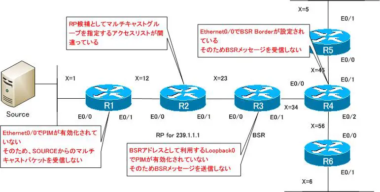
SOURCEが接続されているEthernet0/0でPIM-SMが有効化されていないので、SOURCEから送信されたマルチキャストパケットをルーティングできない
【R2】
RP候補の設定で関連づけるアクセスリストの設定が間違っているため、239.1.1.1ではなく239.1.0.1のRPとしてC-RP-Advertiseメッセージを送信している。そのため、すべてのルータで239.1.1.1のRPとしてR2を認識できない
【R3】
BSR候補としてLoopback0を送信元アドレスのBSRメッセージを送信する設定を行っているが、Loopback0でPIM-SMを有効化していないため、BSRメッセージを送信しない。そのため、すべてのルータでBSRのアドレスを認識できない。
【R4】
Ethernet0/0でBSR Borderの設定がされているため、BSRメッセージを受信しない。そのため、R4以降のルータはBSRのアドレスを認識できない。
すべてのルータで239.1.1.1のRPアドレスを正しく認識して、ルーティングできるようにするためにはどのように設定を修正すればよいですか?
R1
interface Ethernet0/0
 ip pim sparse-mode
R2
no access-list 1
access-list 1 permit 239.1.1.1
R3
interface Loopback0
 ip pim sparse-mode
R4
interface Ethernet0/0
 no ip pim bsr-border
ワンポイント
- マルチキャストパケットの転送経路上のインタフェースすべてでPIMを有効化しなければいけない
- BSRやAuto RPでLoopbackのアドレスを利用するときはLoopbackインタフェースでもPIMを有効にしなければいけない
- BSR BorderによってBSRメッセージが届く範囲を制限できる
解説
4台のルータに複合的に設定ミスを仕込んでいるので、かなり難しい問題です。トラブルの切り分けと修復は、次の2つの段階で考えていくと効果的でしょう。
- RPアドレスの認識(BSR)
- マルチキャストパケットのルーティング
【RPアドレスの認識(BSR)】
まず、PIM-SMではルーティングするマルチキャストグループのRPアドレスをすべてのルータで認識していなければいけません。しかし、各ルータでは239.1.1.1のRPアドレスをまったく認識できていません。今回の構成では、RPの学習をBSRで行っているので、まずはBSRで正しく239.1.1.1のRPアドレスをすべてのルータで認識できるように考えていきます。ここでさらに次の2つの段階に分けて考えます。
- BSRの認識について
- RPの認識について
<BSRの認識について>
BSRでは、BSR候補のルータが定期的にBSRメッセージを送信して最適なBSRを選出します。今回の構成では、R3がBSR候補として設定されています。R3は定期的(60秒ごと)にBSRメッセージを送信して、自身がBSR候補であることを通知するはずです。ですが、R3は実際にはBSRメッセージを送信していません。このことは、R3でshow ip pim bsr-routerを見るとよく分かります。
R3 show ip pim bsr-router
R3#show ip pim bsr-router
PIMv2 Bootstrap information
This system is a candidate BSR
  Candidate BSR interface Loopback0
    PIMv2 is not configured - BSR messages not originated
R3のLoopback0のインタフェースをBSRアドレスとして設定しているのですが、R3のLoopback0ではPIMが有効化されていません。そのため、R3はBSRメッセージを送信していないことが分かります。BSRアドレスとして利用するインタフェースも、次のようにPIMを有効化しなければいけません。
R3 Loopback0でPIM-SMを有効化
interface Loopback0
 ip pim sparse-mode
R3 Loopback0でPIM-SMを有効化したあと、show ip pim bsr-routerを見ると、次のようになります。
R3 show ip pim bsr-router(Loopback0でPIM有効化)
R3#show ip pim bsr-router
PIMv2 Bootstrap information
This system is the Bootstrap Router (BSR)
  BSR address: 192.168.0.3 (?)
  Uptime:      00:00:10, BSR Priority: 0, Hash mask length: 0
  Next bootstrap message in 00:00:50
R3からBSRメッセージが送信されるようになると、R1、R2はBSRアドレスを認識できるようになります。
R1 show ip pim bsr-router
R1#show ip pim bsr-router
PIMv2 Bootstrap information
  BSR address: 192.168.0.3 (?)
  Uptime:      00:02:03, BSR Priority: 0, Hash mask length: 0
  Expires:     00:02:06
R2 show ip pim bsr-router
R2#show ip pim bsr-router
PIMv2 Bootstrap information
  BSR address: 192.168.0.3 (?)
  Uptime:      00:02:40, BSR Priority: 0, Hash mask length: 0
  Expires:     00:01:29
  Candidate RP: 192.168.0.2(Loopback0)
    Holdtime 12 seconds
    Advertisement interval 5 seconds
    Next advertisement in 00:00:03
    Group acl: 1
ですが、R4、R5、R6はBSRアドレスを認識できていません。これは、R4 Ethernet0/0でBSR Borderが設定されているためです。R4でshow ip pim interface ethernet0/0 detailコマンドを確認するとわかります。
R4 show ip pim interface ethernet0/0 detail
R4#show ip pim interface ethernet 0/0 detail
Ethernet0/0 is up, line protocol is up
  Internet address is 192.168.34.4/24
  Multicast switching: fast
  Multicast packets in/out: 0/0
  Multicast TTL threshold: 0
  PIM: enabled
    PIM version: 2, mode: sparse
    PIM DR: 192.168.34.4 (this system)
    PIM neighbor count: 1
    PIM Hello/Query interval: 30 seconds
    PIM Hello packets in/out: 136/136
    PIM State-Refresh processing: enabled
    PIM State-Refresh origination: disabled
    PIM NBMA mode: disabled
    PIM ATM multipoint signalling: disabled
    PIM domain border: enabled
  Multicast Tagswitching: disabled
BSR BorderはBSRメッセージが届く範囲を制限するための機能です。通常、BSRメッセージはマルチキャストネットワーク全体にフラッディングされていきます。BSR Borderが設定されているインタフェースではBSRメッセージ受信しません。また、BSR BorderのインタフェースにBSRメッセージを転送しません。
R4、R5、R6でもBSRアドレスを認識できるようにするためには、R4 Ethernet0/0のBSR Borderを無効化します。
R4 Ethernet0/0でBSR Borderを無効化
interface Ethernet0/0
 no ip pim bsr-border
BSR Borderを無効化すると、次のようにR4、R5、R6でもBSRアドレスを認識できるようになります。
R4 show ip pim bsr-router
R4#show ip pim bsr-router
PIMv2 Bootstrap information
  BSR address: 192.168.0.3 (?)
  Uptime:      00:00:38, BSR Priority: 0, Hash mask length: 0
  Expires:     00:01:31
R5 show ip pim bsr-router
R5#show ip pim bsr-router
PIMv2 Bootstrap information
  BSR address: 192.168.0.3 (?)
  Uptime:      00:01:42, BSR Priority: 0, Hash mask length: 0
  Expires:     00:01:27
R6 show ip pim bsr-router
R6#show ip pim bsr-router
PIMv2 Bootstrap information
  BSR address: 192.168.0.3 (?)
  Uptime:      00:02:10, BSR Priority: 0, Hash mask length: 0
  Expires:     00:01:59
<RPの認識について>
ここまでですべてのルータでBSRアドレスとしてR3(192.168.0.3)を認識しています。そして、RP候補のR2はR3(192.168.0.3)に対して、自身が239.1.1.1のRPであることをC-RP-Advertiseメッセージで通知します。BSRであるR3はBSRメッセージに239.1.1.1のRPアドレスも含めてアドバタイズします。そして、最終的にすべてのルータは239.1.1.1のRPアドレスを認識できるようになるはずです。ところが、R3でRPアドレスの情報を見ると239.1.1.1ではなく239.1.0.1のグループのRPアドレスの認識になってしまっています。
R3 show ip pim rp-mapping
R3#show ip pim rp mapping
PIM Group-to-RP Mappings
This system is the Bootstrap Router (v2)

Group(s) 239.1.0.1/32
  RP 192.168.0.2 (?), v2
    Info source: 192.168.23.2 (?), via bootstrap, priority 0, holdtime 12
         Uptime: 00:20:10, expires: 00:00:08
BSRではC-RP-Advertiseメッセージ内のRPの情報を勝手に書き換えることはしないので、RP候補であるR2での設定ミスが考えられます。そこでR2でRP候補の設定を確認するために、show ip pim bsr-routerとshow access-listコマンドを使います。
R2 show ip pim bsr-router/show access-list
R2#show ip pim bsr-router
PIMv2 Bootstrap information
  BSR address: 192.168.0.3 (?)
  Uptime:      00:24:00, BSR Priority: 0, Hash mask length: 0
  Expires:     00:01:10
  Candidate RP: 192.168.0.2(Loopback0)
    Holdtime 12 seconds
    Advertisement interval 5 seconds
    Next advertisement in 00:00:02
    Group acl: 1
R2#show access-list
Standard IP access list 1
    10 permit 239.1.0.1
これを見ると、R2でアクセスリストの設定が間違っていることが分かります。R2のアクセスリストを修正します。
R2 アクセスリストの修正
no access-list 1
access-list 1 permit 239.1.1.1
ここまでで、すべてのルータでBSRアドレスとしてR3の192.168.0.3を認識します。そして、すべてのルータで239.1.1.1のRPアドレスとしてR2の192.168.0.2を認識します。
【マルチキャストパケットのルーティング】
すべてのルータでBSRもRPもきちんと認識しているのですが、SOURCEから239.1.1.1にパケットを送信してもきちんとルーティングされません。
SOURCE ping 239.1.1.1
SOURCE#ping 239.1.1.1 repeat 100

Type escape sequence to abort.
Sending 100, 100-byte ICMP Echos to 239.1.1.1, timeout is 2 seconds:
...................................
R1でSOURCEからの239.1.1.1のマルチキャストパケットを受信すると、(192.168.1.100,239.1.1.1)エントリを作成するはずですが、できていません。
R1 show ip mroute 239.1.1.1
R1#show ip mroute 239.1.1.1
Group 239.1.1.1 not found
これはR1 Ethernet0/0でPIMが有効化されていないためです。R1でshow ip pim interfaceを見ると、Ethernet0/0でPIMが有効化されていないことが分かります。
R1 show ip pim interface
R1#show ip pim interface

Address          Interface                Ver/   Nbr    Query  DR     DR
                                          Mode   Count  Intvl  Prior
192.168.0.1      Loopback0                v2/S   0      30     1      192.168.0.1
192.168.12.1     Ethernet0/1              v2/S   1      30     1      192.168.12.2
PIMが有効化されていないインタフェースではマルチキャストパケットを受信できません。PIMを有効化することで、該当のインタフェースでマルチキャストパケットを受信できるようになります。そのため、マルチキャストパケットの転送経路上のすべてのインタフェースでPIMを有効化することが、マルチキャストルーティングを行うための大前提です。正しくマルチキャストルーティングするためにR1 Ethernet0/0でPIMを有効化します。
R1 Ethernet0/0でPIMを有効化
interface Ethernet0/0
 ip pim sparse-mode
その後、SOURCEから239.1.1.1のマルチキャストパケットを送信すれば、正常にルーティングされることが分かります。
SOURCE ping 239.1.1.1
SOURCE#ping 239.1.1.1 repeat 100

Type escape sequence to abort.
Sending 100, 100-byte ICMP Echos to 239.1.1.1, timeout is 2 seconds:

Reply to request 0 from 192.168.46.6, 116 ms
Reply to request 0 from 192.168.45.5, 116 ms
Reply to request 1 from 192.168.45.5, 104 ms
Reply to request 1 from 192.168.46.6, 108 ms
【まとめ】
最後にまとめです。R1~R4での設定ミスを次の図にまとめています。

IPマルチキャストの仕組み
- ユニキャスト/ブロードキャスト/マルチキャストの振り返り
- IPマルチキャストの用途 ~同じデータの同報~
- マルチキャストグループへの参加 ~マルチキャストデータを受信できるようにする~
- マルチキャストアドレス ~レイヤ3とレイヤ2のマルチキャストアドレス~
- IGMPの概要 ~マルチキャストグループへの参加を通知~
- IGMPの仕組み
- IGMPの設定と確認コマンド
- IGMPスヌーピング
- マルチキャストルーティングの概要
- ディストリビューションツリー
- RPFチェック
- PIM-DMの仕組み
- PIM-DMの設定と確認コマンド
- PIM-SMの仕組み ~ディストリビューションツリー作成~
- PIM-SMの仕組み ~ディストリビューションツリー作成例~
- PIM-SMの設定と確認コマンド
- PIM-SM ダイナミックなRPの設定 ~Auto RP/BSRの概要~
- PIM-SM AutoRPの設定例
- PIM-SM BSRの設定例
- Bidirectional PIMの設定と確認コマンド
- PIM SSMの設定と確認コマンド
- PIM-SMの設定演習 [スタティックRP]
- PIM-SMの設定演習 [Auto RP]
- PIM-SMの設定演習 [BSR]
- PIM-SMの設定演習 [Bidirectional PIM]
- PIM-SMの設定演習 [SSM]
- PIM-SMの設定演習 [トラブルシュート]
- Anycast RP ~RPの負荷分散~
- Anycast RPの設定と確認コマンド
- Anycast RPの設定例
- マルチキャストパケットの転送経路の制御 ~ip mrouteコマンド~
- ip multicast rate-limitコマンド ~マルチキャストパケットのレート制限~
- ip multicast rate-limitコマンドの設定例
- IGMPレポートの制限
- PIM-SM 設定ミスの切り分けと修正 Part1
- PIM-SM 設定ミスの切り分けと修正 Part2
- PIM-SM 設定ミスの切り分けと修正 Part3
