
Table of Contents
概要
FVRFを利用するVRF-awareなDMVPNの設定例です。マルチポイントGREトンネルでのNHRPの設定の意味を理解しましょう。
関連記事
ネットワーク構成
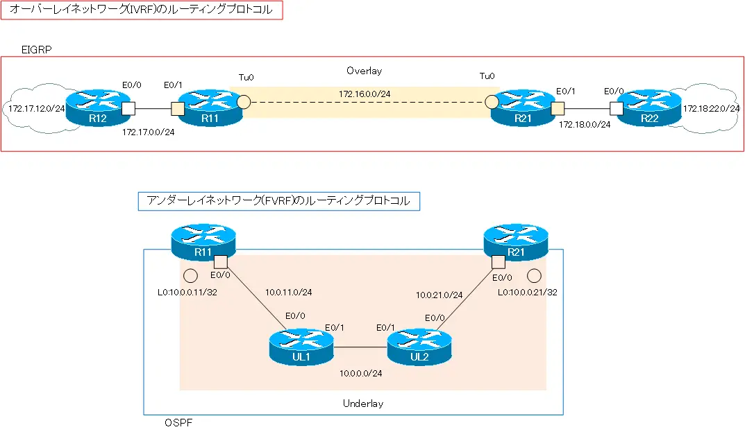
次のネットワーク構成を考えます。「[FVRFの仕組み] IPSec VTI : FVRFあり 設定例」と同じネットワーク構成です。このネットワーク構成のアンダーレイネットワークはインターネットではありませんが、インターネットだと想定します。また、マルチポイントGREトンネルとしますが、話をシンプルにするためにオーバーレイネットワークにはR11/R21のみです。

設定条件
R11-R12間でDMVPNのオーバーレイネットワークを構築します。R11をNHS(Next Hop Server)にします。R12はNHC(Next Hop Client)です。そして、オーバーレイネットワークとアンダーレイネットワークをVRFで分離します。VRFとして、以下のような設定を行います。
| ルータ | VRF名 | RD | インタフェース |
|---|---|---|---|
| R11 | FVRF | 65001:100 | Lo0 Eth0/0 |
| IVRF | 65001:200 | Tunnel0 Eth0/1 | |
| R21 | FVRF | 65001:100 | Lo0 Eth0/0 |
| IVRF | 65001:200 | Tunnel0 Eth0/1 |
また、オーバーレイネットワークのIVRFとアンダーレイネットワークのFVRFのアドレス範囲は、重複しないようにしています。IVRFは、172.16.x.xおよび172.17.x.x、172.18.x.xといったクラスBのプライベートアドレスでアドレッシングしています。そして、FVRFは、10.x.x.xのクラスAのプライベートアドレスでアドレッシングしています。
ルーティングプロトコルとして、IVRFはEIGRPを利用し、FVRFではOSPFを利用します。
| アドレス範囲 | ルーティングプロトコル | |
|---|---|---|
| オーバーレイネットワーク(IVRF) | 172.16.0.0/16 172.17.0.0/16 172.18.0.0/16 | EIGRP |
| アンダーレイネットワーク(FVRF) | 10.0.0.0/8 | OSPF |
オーバーレイネットワークのデータをIPSecで暗号化して、アンダーレイネットワーク上を転送します。IPSecの各種パラメータは、以下の通りとします。
| 暗号化アルゴリズム | 3DES |
| ハッシュアルゴリズム | MD5 |
| ピア認証 | PSK |
| DHグループ | 2 |
| セキュリティプロトコル | ESP |
| 暗号化アルゴリズム | 3DES |
| ハッシュアルゴリズム | MD5 |
初期設定
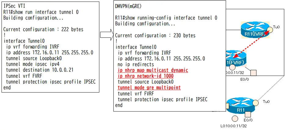
R11-R21間でIPSec VTIによるオーバーレイネットワークをVRFを分離している状態から開始します。これは、 「[FVRFの仕組み] IPSec VTI : FVRFあり 設定例」 の完了段階です。IPSec VTIからDMVPNへの変更のための設定にフォーカスします。
R11 設定抜粋(Click)
hostname R11
!
ip vrf FVRF
 rd 65001:100
!
ip vrf IVRF
 rd 65001:200
!
crypto keyring KEY vrf FVRF
  pre-shared-key address 10.0.0.21 key cisco
!
crypto isakmp policy 10
 encr 3des
 hash md5
 authentication pre-share
 group 2
!
crypto ipsec transform-set TS esp-3des esp-md5-hmac
 mode tunnel
!
crypto ipsec profile IPSEC
 set transform-set TS
!

interface Loopback0
 ip vrf forwarding FVRF
 ip address 10.0.0.11 255.255.255.255
!
interface Tunnel0
 ip vrf forwarding IVRF
 ip address 172.16.0.11 255.255.255.0
 tunnel source Loopback0
 tunnel mode ipsec ipv4
 tunnel destination 10.0.0.21
 tunnel vrf FVRF
 tunnel protection ipsec profile IPSEC
!
interface Ethernet0/0
 ip vrf forwarding FVRF
 ip address 10.0.11.11 255.255.255.0
!
interface Ethernet0/1
 ip vrf forwarding IVRF
 ip address 172.17.0.11 255.255.255.0
!
router eigrp 1
 !
 address-family ipv4 vrf IVRF autonomous-system 1
  network 172.16.0.0
  network 172.17.0.0
 exit-address-family
 eigrp router-id 11.11.11.11
!
router ospf 1 vrf FVRF
 router-id 11.11.11.11
 network 10.0.0.11 0.0.0.0 area 0
 network 10.0.11.11 0.0.0.0 area 0
R21 設定抜粋(Click)
hostname R21
!
ip vrf FVRF
 rd 65100:100
!
ip vrf IVRF
 rd 65100:200
!
crypto keyring KEY vrf FVRF
  pre-shared-key address 10.0.0.11 key cisco
!
crypto isakmp policy 10
 encr 3des
 hash md5
 authentication pre-share
 group 2
!
crypto ipsec transform-set TS esp-3des esp-md5-hmac
 mode tunnel
!
crypto ipsec profile IPSEC
 set transform-set TS
!
interface Loopback0
 ip vrf forwarding FVRF
 ip address 10.0.0.21 255.255.255.255
!
interface Tunnel0
 ip vrf forwarding IVRF
 ip address 172.16.0.21 255.255.255.0
 tunnel source Loopback0
 tunnel mode ipsec ipv4
 tunnel destination 10.0.0.11
 tunnel vrf FVRF
 tunnel protection ipsec profile IPSEC
!
interface Ethernet0/0
 ip vrf forwarding FVRF
 ip address 10.0.21.21 255.255.255.0
!
interface Ethernet0/1
 ip vrf forwarding IVRF
 ip address 172.18.0.21 255.255.255.0
!
router eigrp 1
 !
 address-family ipv4 vrf IVRF autonomous-system 1
  network 172.16.0.0
  network 172.18.0.0
 exit-address-family
 eigrp router-id 21.21.21.21
!
router ospf 1 vrf FVRF
 router-id 21.21.21.21
 network 10.0.0.21 0.0.0.0 area 0
 network 10.0.21.21 0.0.0.0 area 0
R12 設定抜粋(Click)
hostname R12
!
interface Loopback0
 ip address 172.17.12.12 255.255.255.0
 ip ospf network point-to-point
!
interface Ethernet0/0
 ip address 172.17.0.12 255.255.255.0
!
router eigrp 1
 network 172.17.0.0
 eigrp router-id 12.12.12.12
R22 設定抜粋(Click)
hostname R22
!
interface Loopback0
 ip address 172.18.22.22 255.255.255.0
 ip ospf network point-to-point
!
interface Ethernet0/0
 ip address 172.18.0.22 255.255.255.0
!
router eigrp 1
 network 172.18.0.0
 eigrp router-id 22.22.22.22
UL1 設定抜粋(Click)
hostname UL1
!
interface Ethernet0/0
 ip address 10.0.11.1 255.255.255.0
!
interface Ethernet0/1
 ip address 10.0.0.1 255.255.255.0
!
router ospf 1
 router-id 1.1.1.1
 network 10.0.0.0 0.255.255.255 area 0
UL2 設定抜粋(Click)
hostname UL2
!
interface Ethernet0/0
 ip address 10.0.21.2 255.255.255.0
!
interface Ethernet0/1
 ip address 10.0.0.2 255.255.255.0
!
router ospf 1
 router-id 2.2.2.2
 network 10.0.0.0 0.255.255.255 area 0
設定と確認
Step1: R11 mGRE NHSの設定
R11のTunnel0インタフェースをmGREに変更します。R11はNHSとして、オーバーレイアドレスをアンダーレイアドレスの対応を管理します。また、Tunnel0から出力するマルチキャストパケットは、NHRPでダイナミックに登録されたNHCのアンダーレイアドレスでカプセル化します。
R11 mGRE NHSの設定
interface Tunnel 0
 no tunnel destination
 tunnel mode gre multipoint
 ip nhrp network-id 1000
 ip nhrp map multicast dynamic
Step2: R21 mGRE NHCの設定
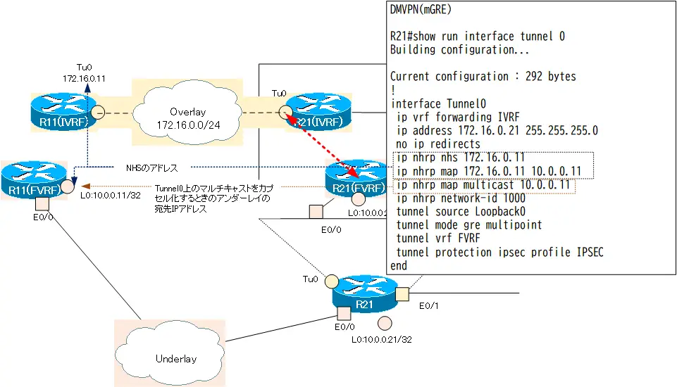
R21のTunnel0インタフェースをmGREに変更します。R21はNHCとして設定します。オーバーレイアドレスとアンダーレイアドレスの対応を管理するNHSとしてR11を指定します。また、Tunnel0から出力するマルチキャストパケットは、R11のアンダーレイアドレス(10.0.0.11)でカプセル化します。
R21 mGRE NHCの設定
interface Tunnel 0
 no tunnel destination
 tunnel mode gre multipoint
 ip nhrp network-id 1000
 ip nhrp nhs 172.16.0.11
 ip nhrp map 172.16.0.11 10.0.0.11
 ip nhrp map multicast 10.0.0.11
Step3: crypto keyringの設定
R11とR21だけなので、現在のcrypto keyringの設定のままでもIPSecの通信は可能です。ダイナミックなIPSecピアを確立するために、crypto keyringの設定でピアのIPアドレスは明示的に指定しないように変更します。
R11 crypto keyringの設定
crypto keyring KEY vrf FVRF
  no pre-shared-key address 10.0.0.21 key cisco
  pre-shared-key address 0.0.0.0 0.0.0.0 key cisco
R21 crypto keyringの設定
crypto keyring KEY vrf FVRF
  no pre-shared-key address 10.0.0.11 key cisco
  pre-shared-key address 0.0.0.0 0.0.0.0 key cisco
Step4: IPSecトランスフォームセットの設定
カプセル化するヘッダのオーバーヘッドを少なくするために、現在のIPSecトランスフォームセット「TS」のモードをトランスポートモードに変更します。
R11/R21 IPSecトランスフォームセットの設定
crypto ipsec transform-set TS esp-3des esp-md5-hmac
 mode transport
Step5: DMVPNの確認
以下のshowコマンドで、DMVPNの設定と動作を確認します。
- show interface tunnel 0
- show dmvpn
- show ip nhrp
- show ip eigrp vrf IVRF neighbor
- show ip route vrf IVRF
R11では、次のような内容です。
R11 DMVPNの確認
R11#show interfaces tunnel 0
Tunnel0 is up, line protocol is up
  Hardware is Tunnel
  Internet address is 172.16.0.11/24
  MTU 17916 bytes, BW 100 Kbit/sec, DLY 50000 usec,
     reliability 255/255, txload 1/255, rxload 1/255
  Encapsulation TUNNEL, loopback not set
  Keepalive not set
  Tunnel linestate evaluation up
  Tunnel source 10.0.0.11 (Loopback0)
   Tunnel Subblocks:
      src-track:
         Tunnel0 source tracking subblock associated with Loopback0
          Set of tunnels with source Loopback0, 1 member (includes iterators), on interface
  Tunnel protocol/transport multi-GRE/IP
    Key disabled, sequencing disabled
    Checksumming of packets disabled
  Tunnel TTL 255, Fast tunneling enabled
  Tunnel transport MTU 1476 bytes
  Tunnel transmit bandwidth 8000 (kbps)
  Tunnel receive bandwidth 8000 (kbps)
  Tunnel protection via IPSec (profile "IPSEC")
~省略~
R11#show dmvpn
Legend: Attrb --> S - Static, D - Dynamic, I - Incomplete
        N - NATed, L - Local, X - No Socket
        T1 - Route Installed, T2 - Nexthop-override
        C - CTS Capable
        # Ent --> Number of NHRP entries with same NBMA peer
        NHS Status: E --> Expecting Replies, R --> Responding, W --> Waiting
        UpDn Time --> Up or Down Time for a Tunnel
==========================================================================

Interface: Tunnel0, IPv4 NHRP Details
Type:Hub, NHRP Peers:1,

 # Ent  Peer NBMA Addr Peer Tunnel Add State  UpDn Tm Attrb
 ----- --------------- --------------- ----- -------- -----
     1 10.0.0.21           172.16.0.21    UP 00:20:19     D

R11#show ip nhrp
172.16.0.21/32 (IVRF) via 172.16.0.21
   Tunnel0 created 00:20:23, expire 01:39:36
   Type: dynamic, Flags: unique registered used nhop
   NBMA address: 10.0.0.21
R11#show ip eigrp vrf IVRF neighbors
EIGRP-IPv4 Neighbors for AS(1) VRF(IVRF)
H   Address                 Interface              Hold Uptime   SRTT   RTO  Q  Seq
                                                   (sec)         (ms)       Cnt Num
1   172.16.0.21             Tu0                      14 00:20:16  258  1548  0  14
0   172.17.0.12             Et0/1                    12 00:28:14    8   100  0  8
R11#show ip route vrf IVRF

Routing Table: IVRF
~省略~

Gateway of last resort is not set

      172.16.0.0/16 is variably subnetted, 2 subnets, 2 masks
C        172.16.0.0/24 is directly connected, Tunnel0
L        172.16.0.11/32 is directly connected, Tunnel0
      172.17.0.0/16 is variably subnetted, 3 subnets, 2 masks
C        172.17.0.0/24 is directly connected, Ethernet0/1
L        172.17.0.11/32 is directly connected, Ethernet0/1
D        172.17.12.0/24 [90/409600] via 172.17.0.12, 00:28:19, Ethernet0/1
      172.18.0.0/24 is subnetted, 2 subnets
D        172.18.0.0 [90/26905600] via 172.16.0.21, 00:20:22, Tunnel0
D        172.18.22.0 [90/27033600] via 172.16.0.21, 00:20:22, Tunnel0
mGREのTunnel0上でR21とEIGRPネイバーとなり、オーバーレイネットワーク経由のルート情報を学習できていることがわかります。
Step6: 通信確認
オーバーレイネットワークの通信が正常にできることを確認します。R12からR22へPingを実行します。
R12からR22へPing
R12#ping 172.18.22.22 source 172.17.12.12
Type escape sequence to abort.
Sending 5, 100-byte ICMP Echos to 172.18.22.22, timeout is 2 seconds:
Packet sent with a source address of 172.17.12.12
!!!!!
Success rate is 100 percent (5/5), round-trip min/avg/max = 1/1/2 ms
オーバーレイネットワークの通信が正常にできていることがわかります。
設定のまとめ
R11/R21のDMVPN(VRF-aware)に関連する設定の抜粋は以下のようになります。
R11 DMVPN(VRF-aware) 設定のまとめ
hostname R11
!
ip vrf FVRF
 rd 65001:100
!
ip vrf IVRF
 rd 65001:200
!
crypto keyring KEY vrf FVRF
  pre-shared-key address 0.0.0.0 0.0.0.0 key cisco
!
crypto isakmp policy 10
 encr 3des
 hash md5
 authentication pre-share
 group 2
!
crypto ipsec transform-set TS esp-3des esp-md5-hmac
 mode transport
!
crypto ipsec profile IPSEC
 set transform-set TS
!
interface Loopback0
 ip vrf forwarding FVRF
 ip address 10.0.0.11 255.255.255.255
!
interface Tunnel0
 ip vrf forwarding IVRF
 ip address 172.16.0.11 255.255.255.0
 no ip redirects
 ip nhrp map multicast dynamic
 ip nhrp network-id 1000
 tunnel source Loopback0
 tunnel mode gre multipoint
 tunnel vrf FVRF
!
interface Ethernet0/0
 ip vrf forwarding FVRF
 ip address 10.0.11.11 255.255.255.0
!
interface Ethernet0/1
 ip vrf forwarding IVRF
 ip address 172.17.0.11 255.255.255.0
!
router eigrp 1
 !
 address-family ipv4 vrf IVRF autonomous-system 1
  network 172.16.0.0
  network 172.17.0.0
 exit-address-family
 eigrp router-id 11.11.11.11
!
router ospf 1 vrf FVRF
 router-id 11.11.11.11
 network 10.0.0.11 0.0.0.0 area 0
 network 10.0.11.11 0.0.0.0 area 0
R21 DMVPN(VRF-aware) 設定のまとめ
hostname R21
!
ip vrf FVRF
 rd 65100:100
!
ip vrf IVRF
 rd 65100:200
!
crypto keyring KEY vrf FVRF
  pre-shared-key address 0.0.0.0 0.0.0.0 key cisco
!
crypto isakmp policy 10
 encr 3des
 hash md5
 authentication pre-share
 group 2
!
crypto ipsec transform-set TS esp-3des esp-md5-hmac
 mode transport
!
crypto ipsec profile IPSEC
 set transform-set TS
!
interface Loopback0
 ip vrf forwarding FVRF
 ip address 10.0.0.21 255.255.255.255
!
interface Tunnel0
 ip vrf forwarding IVRF
 ip address 172.16.0.21 255.255.255.0
 no ip redirects
 ip nhrp map 172.16.0.11 10.0.0.11
 ip nhrp map multicast 10.0.0.11
 ip nhrp network-id 1000
 ip nhrp nhs 172.16.0.11
 tunnel source Loopback0
 tunnel mode gre multipoint
 tunnel vrf FVRF
!
interface Ethernet0/0
 ip vrf forwarding FVRF
 ip address 10.0.21.21 255.255.255.0
!
interface Ethernet0/1
 ip vrf forwarding IVRF
 ip address 172.18.0.21 255.255.255.0
!
router eigrp 1
 !
 address-family ipv4 vrf IVRF autonomous-system 1
  network 172.16.0.0
  network 172.18.0.0
 exit-address-family
 eigrp router-id 21.21.21.21
!
router ospf 1 vrf FVRF
 router-id 21.21.21.21
 network 10.0.0.21 0.0.0.0 area 0
 network 10.0.21.21 0.0.0.0 area 0

IPルーティング応用
- DNSラウンドロビン方式の負荷分散
- 負荷分散装置(ロードバランサ)の仕組み
- ルーティングプロセス ~実行中のルーティングプロトコル用のプログラム~
- 複数のルーティングプロトコルの利用
- 再配送(再配布) ~ルーティングドメイン境界で必須の設定~
- Cisco再配送(再配布)の設定 ~redistributeコマンド~
- Cisco 再配送の設定例 ~OSPFとRIPの双方向再配送~
- 再配送 設定ミスの切り分けと修正 Part1
- 再配送 設定ミスの切り分けと修正 Part2
- 再配送 設定ミスの切り分けと修正 Part3
- 再配送 設定ミスの切り分けと修正 Part4
- 再配送 設定ミスの切り分けと修正 Part5
- 再配送 設定ミスの切り分けと修正 Part6
- オフセットリスト(offset-list) ~ルート情報のメトリックを加算~
- オフセットリストの設定例 RIP
- オフセットリストの設定例 EIGRP
- ルートフィルタの概要
- ルートフィルタのポイント
- ディストリビュートリストによるルートフィルタの設定
- Ciscoディストリビュートリストによるルートフィルタの設定例
- プレフィクスリスト(prefix-list)によるルートフィルタの設定
- Ciscoプレフィクスリストによるルートフィルタの設定例
- Ciscoルートマップ(route-map)の概要 ~何をどう処理するか~
- Ciscoルートマップの設定
- Ciscoルートマップ(route-map)設定のポイント
- Ciscoルートマップによる再配送時のルート制御の設定例
- ポリシーベースルーティングの設定例
- GREトンネルインタフェース ~仮想的なポイントツーポイント接続~
- GREトンネルインタフェースの設定例
- GREトンネルの注意点 ~フラッピングしないように~
- オーバーレイネットワークとアンダーレイネットワーク
- ルート制御 ケーススタディ Part1
- ルート制御 ケーススタディ Part2
- ルート制御 ケーススタディ Part3
- VRF/VRF-Liteの概要 ~仮想的にルータを分割する~
- VRFの設定と確認コマンド [Cisco]
- VRF-Liteによるレイヤ3VPNの設定例 [Cisco]
- VRFルートリーク(スタティックルート)
- VRFルートリーク(スタティックルート)の設定例
- VRFルートリーク(MP-BGP)
- VRFルートリーク(MP-BGP)の設定例
- [FVRFの仕組み] FVRF(Front door VRF)とは
- [FVRFの仕組み] ポイントツーポイントGREトンネル:FVRFなし
- [FVRFの仕組み] ポイントツーポイントGREトンネル : FVRFあり(tunnel vrfコマンド)
- [FVRFの仕組み] IPSec VTI : FRVRFあり
- [FVRFの仕組み] IPSec VTI : FVRFあり 設定例
- [FVRFの仕組み] DMVPN : FVRFあり
- [FVRFの仕組み] DMVPN : FVRFあり 設定例 Part1
- [FVRFの仕組み] DMVPN : FVRFあり 設定例 Part2
- tunnel vrfコマンド
- tunnel vrfコマンドの設定例
- [演習] ルーティングループの防止
- [演習] 企業ネットワーク構築演習 Part1:拠点1の構築
- [演習] 企業ネットワーク構築演習 Part2:拠点2/拠点3の構築
- [演習] 企業ネットワーク構築演習 Part3:広域イーサネットの接続
- [演習] 企業ネットワーク構築演習 Part4:インターネット(AS1/AS2)の構築
- [演習] 企業ネットワーク構築演習 Part5:インターネットへの接続
- [演習] 企業ネットワーク構築演習 Part6:インターネットVPNの構築